Continue to Site

Eng-Tips is the largest engineering community on the Internet

Intelligent Work Forums for Engineering Professionals

  • Congratulations SSS148 on being selected by the Eng-Tips community for having the most helpful posts in the forums last week. Way to Go!

Datum target cylinders? 5

Status
Not open for further replies.

semiond

Mechanical
Jan 9, 2011
176
Hello all,
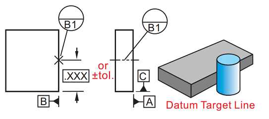
Fig. 4-49 in ASME Y-14.5-2009 displays the use of datum target spheres.
I wanted to know if it is also acceptable to use datum target cylinders. I haven't seen an example in the standard and i'm not sure whether it is allowed or not.
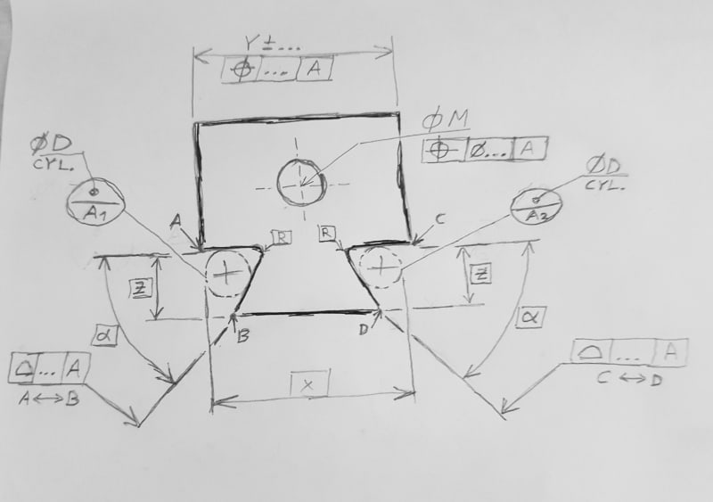
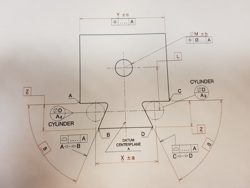
One case where this could be useful is parts with dovetail geometry (see picture); both for controling the dovetail taper surfaces themselves (profile of a surface referencing datum target cylinders with basic dimension distances) and for constraining degrees of freedom and establishing the DRF for the entire part.
20180604_062952_eq1jgs.png
 
Replies continue below

Recommended for you

Capture_sp6h7k.png


Is this cylinder enough?

"For every expert there is an equal and opposite expert"
Arthur C. Clarke Profiles of the future
 
CheckerHater,
I'm not sure what you meant to ask but the image above is just something i found on the web to display the relevance of cylindrical gauges to parts with dovetail features (they are usually dimensioned through them). My question is general and theoretical. However, if more specification is needed - one pair of cylindrical datum targets could be designated A1 and A2 and represent datum A (datum center plane + additional degrees of freedom constrained) similary to how the two spheres in fig. 4-49 in Y14.5 create a datum axis.

Edit: my apologies, i haven't seen the image in your reply earlier, just the text. I now understand better what you were asking, but the explanation above is still relevant.
 
There are generally 3 kinds of datum targets: points, lines and areas.
Points represent contact with spherical datum simulators.
Lines represent contact with cylindrical datum simulators like dowel pins.
Areas represent machined tooling surfaces.
The rest is up to you: you create the fixturing scheme that will serve you the best.
Standard cannot provide all the possible configurations that may be necessary - just the basic ideas.
So if you ask for a reference - it may not be available in standard book for your particular situation.
Or maybe I misunderstood your question.

"For every expert there is an equal and opposite expert"
Arthur C. Clarke Profiles of the future

 
CheckerHater, thank you for the input.
I suppose that fig. 4-49 is a bit unusual, because the spheres that are depicted there do not create datum target points, and their contact form with the conical datum features is actually circular. I will soon prepare an analogical sketch with cylinders for a "legit. or not" inquery.
Thanks again.
 
Measurement over cylinders is often used to make size measurements, which the dovetail example shows. It is used to verify pitch diameters for screw threads and the backlash cut into involute gears.

I have used a cylinder where the mating part was an actual cylinder to determine a location.

What you will find to be difficult is if there is the slightest lack of perfect parallelism between the cylinders. I avoided the problem by measuring the tangent to the cylinder at a fixed location along the cylinder rather than taking a 5 DOF measurement of multiple features and trying to pick out a single DRF from them.

Remember to include errors in the form of the gage pins as part of the tolerance analysis.

The datum targets in 4-49 are the centers of the spheres. The spheres may only contact at 3 points, not even circles.

Edit - from the standard:

(c) a spherical datum feature establishes a datum
feature simulator that creates a datum center point and
constrains three translational degrees of freedom. See
Fig. 4-3, illustration (c).
 
--------------------------------------
4.24.6 Movable Datum Target Symbol

"....In other cases where the datum feature simulator is required to move and where the movement is not normal to the true profile, the movable datum target symbol shall be used and the direction of movement shall be clearly defined. See figures 4-47 and 4-49."
------------------------------------

If the cylinder will be touching two surfaces (corner of the dovetail) you will need to address the above. Normal to the true profile is not clear in this case.
 
3DDave,
Thank you for the measurement tips.

Regarding fig. 4-49, by my interpretation the spheres displayed there do not represent datum target point simulators, but a unique form of datum targets, different from the 3 kinds mentioned by CheckerHater (points, lines, areas). The reason i think so is the spherical diameter designation on the upper halve of the datum target symbol, and them being connected directly to the spheres' contours rather than to points. By analogy, i thought that cylinders could be used too as datum targets (with defined diameters and basic dimension distance between them, or with one of them movable) rather than only as datum target line simulators.

Anyway... i will soon prepare a sketch.
 
20180604_195501_cjn2be.jpg


As promised. Sorry it's handmade. All opinions and comments will be highly appreciated.

Edit: correction to the sketch - D diameters should be basic.
 
AndrewTT said:
If the cylinder will be touching two surfaces (corner of the dovetail) you will need to address the above. Normal to the true profile is not clear in this case.

Correct, thanks for pointing thia out.
 
The cylinders on your drawing don't look like datum targets to me.
Also, if they ARE datum targets, what are datum / datum feature(s) in your set-up?

"For every expert there is an equal and opposite expert"
Arthur C. Clarke Profiles of the future

 
What is the DRF for your hand drawn sketch? Asked another way, the basic dimensions that you will need for the true position of the hole will lead back to what?

The thing about datum targets is that it is not always obvious what the DRF that they establish actually is. This is why in Y14.8 they use clarifying Datum Feature symbols to identify what is being established by the targets. They also use notes to show datum center planes that are established from the targets. See fig. 4-4 & 4-6 (attached)
 
 https://files.engineering.com/getfile.aspx?folder=9159e1fa-8ca1-44a0-ac80-13e9d2ff2565&file=targets_for_forum.docx
semiond,

I too am learning English. Pardon the conffusion. They points at the centers of the spheres are the datums as evdneces by the place the dimsions start.
 
Although technically acccepable, I prefer to NOT have the angled surfaces located from Datum A, which is established from the same angled surfaces - reminds me of which came first the chicken or the egg. Have you considered turning the dimesionson schema "around" and locate the dovetailed surfaces from other part featreus - like the widht Y nad the hole.

Certified Sr. GD&T Professional
 
This fails the same as his previous use of RFS to determine a centerplane. Same concept that only works if the parts are perfect. Otherwise, if the axes of the cylinders are skew there is no defined single solution. Since the cylinders are given a basic separation there is no guarantee they will even touch the part; all references to A can be deleted with no change in interpretation any of it. The features will be subject to a simultaneous requirement with a null datum reference.
 
mkcski,
For now i live in peace with the chicken and the egg dilemma, i'm more concerened about the question if this is acceptable according to ASME or not, because of the unusual use of cylindrical datum targets. As CheckerHater noted, they don't look quite like datum targets (and could be taken for datum target line simulators being displayed on a part drawing when they shouldn't). In any case, even if it is acceptable, i'm not in a hurry to adopt this as a dimensioning scheme.

AndrewTT,
Thanks for bringing up those references from Y14.8 - they are very helpful.
The datums that should be established from the cylinders is a center plane in the middle of the distance between them, and a plane that passes through their axes perpendicular to the center plane.
Below are some modifications i made following your and the others' comments.

3DDave, i took notice of your comment regarding the fixed distance between cylinders, the current sketch adresses this too.

20180605_082941_tm1t8x.jpg
 
semiond,

Is there a specific reason why you decided to reference datum A in both profile callouts?

What if you used profiles with no datum references with addition of SIM REQT notations below both feature control frames. Then, I believe, you would not need X +/-a dimension between cylinder centers - the distance would be adjustable based on movable datum target symbol and the way how A is referenced (that is, RMB) in the other position callouts.
 
pmarc,
You are right, the two profiles should act like a pattern but they shouldn't be located (only oriented) with reference to A each other. I should have removed A from the profile FCF's and add 2X before the profile callout which would be shown on one side only, or use the SIM REQT note as you suggested.

What is your opinion on the legality of the cylindrical datum targets?
 
semiond,
I do not see anything incorrect in the application of cylinders to simulate datum.

In your scenario, usage of movable datum target symbol (although technically not needed as A is referenced RMB in the position callouts) will definitely help.

I am just not sure I like the directly toleranced dimension X over the cylinders...
 
The dimension is needed to control the size of the dovetail.
Would it be better if it was applied tangent to the cylinders instead of the centers?
 
Status
Not open for further replies.

Part and Inventory Search

Sponsor