Continue to Site

Eng-Tips is the largest engineering community on the Internet

Intelligent Work Forums for Engineering Professionals

  • Congratulations IDS on being selected by the Eng-Tips community for having the most helpful posts in the forums last week. Way to Go!

Datum Targets on forging that's machined all over

Status
Not open for further replies.

R1chJC

Marine/Ocean
Apr 15, 2015
51
Hi all,

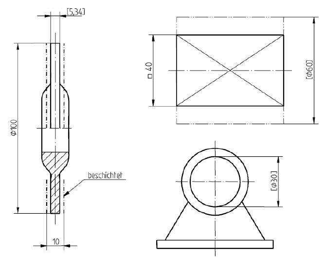
I have a forged wheel rim where all surfaces are subsequently machined, no forged faces are left. The forging looks like a wheel, no surprise there..

Since the part is machined call over, machined faces relative to forging features are not important to me, as long as I end up with a complete wheel.

I cant quite wrap my head around whether this part would benefit from datum targets/points. Being a wheel, the required orientation of the machined outline within the forging is fairly obvious - to me at least.

I'm working to ASME.

Any thoughts would be welcome.


Replies continue below

Recommended for you

Typically there will be some initial features that provide primary orientation and location. I would make a drawing that shows those features relative to targets on the raw casting such that there will be material to clean up. Then another drawing showing the finished machining relative to those initial machined features. While some may complain that this is 'processing' on the drawing, it seems like the best way to provide consistent results.

One thing that won't work is to have the targets just float in mid-air and expect inspectors to deduce where the original surfaces were.
 
Hi 3DDave,

Thanks for your response,

On this machined part, my primary datum is the bearing diameter and the secondary datum is the corresponding bearing abutment shoulder.

So your suggesting identifying datum target points on the forging, and then dimension from those to the two datum's I described above in order to describe the position of the machined part withing the forging?


Generally, yes. There's still plenty of room to mess that up but, done correctly, you should be able to use those same targets to define the other features on the forging so that you can predict how variations between the forging process and the machining process will interact.
 
R1chJC,

ASME allows you to identify manufacturing data as "nonmandatory":

Capture_r0sobj.png


Also:

Capture_2_i3ydmu.png


Since I have no idea how your "wheel" design actually looks like, I leave it to yourself to assign datum targets; I will just illustrate possible relation between temporary and permanent datum features:

Draw2_ayrgvt.jpg


Edit: Sorry, naturally dimensions are diameters :)

"For every expert there is an equal and opposite expert"
Arthur C. Clarke Profiles of the future
 
Per DIN 406-10 dimensions of a part prior to a machining or coating process are indicated by square brackets.
Raw_Part_Dimensions_txpfnf.jpg

This is often used on cast parts that require machining, so would definitely fit here.
You could use that and add a note the square brackets indicate raw/as cast dimensions.
 
How are you holding the part when you machining? How do you fixture the forging in the machining fixture when you start machining?
 
Thanks for the responses;

CheckerHater:
OK I see what your saying. On your example does that mean that don't have to use Datum A, but they could if they wanted? The word non-mandatory suggests a choice? Also, how would an inspector verify that positional tolerance on the final part?
Any reason why I would choose this method over assigning datum targets?

SDETERS
SDETERS said:
How are you holding the part when you machining? How do you fixture the forging in the machining fixture when you start machining?
I agree, i'm asking how best to define this on the drawing.

Thanks Th.Ro. but i'm working to ASME.

 
R1chJC said:
On your example does that mean that don't have to use Datum A, but they could if they wanted?
By all means, no. On your drawing you show datum targets the way that implies 3-jaw chuck, or whatever fixturing you chose.
R1chJC said:
The word non-mandatory suggests a choice?
To some extent. The producer of the forged blank may chose larger or smaller allowance for future machining, so you are giving him that kind of freedom.
R1chJC said:
how would an inspector verify that positional tolerance on the final part?
He wouldn't. The idea of temporary datum features is that they may be destroyed in process. The tolerance may be checked "in process", but not necessarily on final part.

I hope that helps.

"For every expert there is an equal and opposite expert"
Arthur C. Clarke Profiles of the future

 
Thanks CheckerHater,

Its starting to make a bit more sense.

So far my part looks a little like the below:
Forge_t93xc7.jpg


I'm still struggling to decide if i really need to define and relationship between my forged and my final machined part. As long as I get complete clean up and a finished part I'm happy. In my instance the wheel has a deep dish so there is only really one orientation of the forging that will fully enclose the machined part.
 
R1chJC

You could still use it if you define it in the notes: "SQUARE BRACKETS [X.XXX] INDICATE PART DIMENSIONS AS CAST."

Inspection dimensions using the DIN 406-10 inspection symbol are quite common on US drawings:

Inspection_Dimension_cyvz0h.jpg


Sometimes, but not always, accompanied by an explanatory note like this:

Inspection_Dimension_Note_plfxy6.jpg
 
R1chJC,

I've seen two main approaches to this type of problem. One approach is to define the raw forging, and then define a series of modification processes that will hopefully result in the desired end item. The other is to define the end item, and then work backwards and define the input item to each modification process. I usually prefer the second option.

Assume the following scenario:
[ul]
[li]Part number 114 is the raw forging.[/li]
[li]Machining process A takes part number 114 as input and produces part number 115 as output.[/li]
[li]Part number 115 is the partially machined forging.[/li]
[li]Machining process B takes part number 115 as input and produces part number 116 as output.[/li]
[li]Part number 116 is the fully machined end item.[/li]
[/ul]

Part number 116 must be designed to properly fulfill its functional requirements. It sounds like the relationship between the end item surfaces and the forged surfaces (which are no longer present) is not relevant to this. It would probably be desirable to use use functionally relevant surfaces as datum features on the drawing for part number 116.

Machining process B and its input part number 115 must be designed to properly produce the output part number 116. In this process, the part will presumably be located and clamped using surfaces (or portions of surfaces) created by the previous machining process. It would probably be desirable to use those surfaces as datum features on the drawing for part number 115. If they will be fairly accurate, there might not be much benefit in using datum targets instead of complete surfaces.

Machining process A and its input part number 114 must be designed to properly produce the output part number 115. In this process, the part will be located and clamped using portions of surfaces created by the forging process. It would probably be desirable to use those portions of surfaces as datum targets on the drawing for part number 114.


pylfrm
 
Status
Not open for further replies.

Part and Inventory Search

Sponsor