Continue to Site

Eng-Tips is the largest engineering community on the Internet

Intelligent Work Forums for Engineering Professionals

  • Congratulations KootK on being selected by the Eng-Tips community for having the most helpful posts in the forums last week. Way to Go!

Detailing of required reinforcement with slab offset 2

Status
Not open for further replies.

chritsar

Structural
May 9, 2022
11
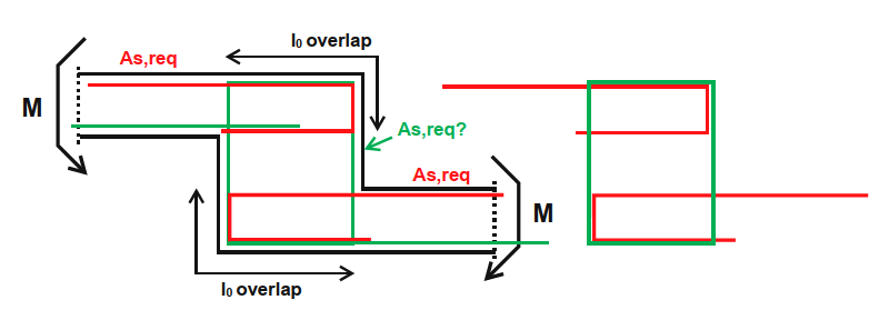
Suppose we have a slab with an offset that at the same time acts as a supporting beam (happens a lot in projects where there is an underground garage for example). In the static analysis the slab is assumed to be continuous. The beam acts as a support therefore the moments in the slab will be negative requiring top reinforcement.

The question: Is it enough to anchor the top reinforcement inside the width of the beam? Or is it necessary to overlap the required reinforcement with the beam stirrups in order to provide continuity of the moment resistance between the top and bottom slabs?

By my estimate, this has to do with the width of the beam (b in the sketch). In sufficiently wide beams (how would that be defined though?) the beam can be assumed as fully rigid and therefore I would expect a mere anchorage of the slab reinforcement to suffice. If the beam is not wide enough (perhaps close to the depth of the slabs) then I would expect a need for overlapping the required reinforcement of the slabs with the beam stirrups so the moment can be fully transferred.

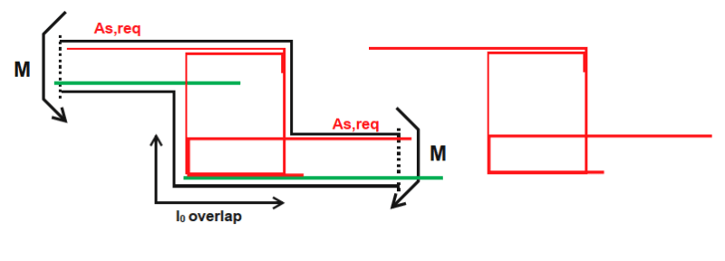
Below I have two sketches: One is the described situation - slab offset as a supporting beam and the second is a typical slab offset with the proposed reinforcement for moment continuity.
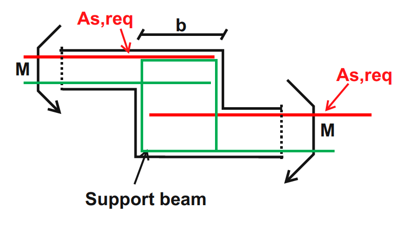
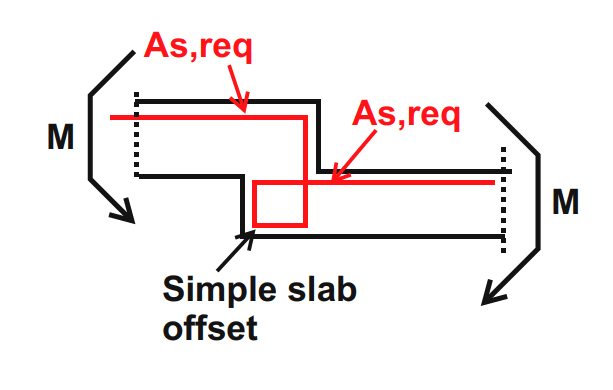
Support_beam_-_offset_tb25zr.png

Simple_slab_offset_dbtclp.png
 
Replies continue below

Recommended for you

I would definitely go for the top option (assuming that the straight laps are sufficient for the required development - probably need hooks in reality)
A lesson here post-earthquake was that slab steps performed badly - the standard detail just had bars cranked twice to make them continuous
These joints opened up and were badly damaged
The recommended detail now is basically what you've drawn at the top - I have used it several times now
I use a standard stirrup with a 4-bar cage running into the page, then return my top and bottom steel in both the upper and lower slabs into the cage with hooks
 
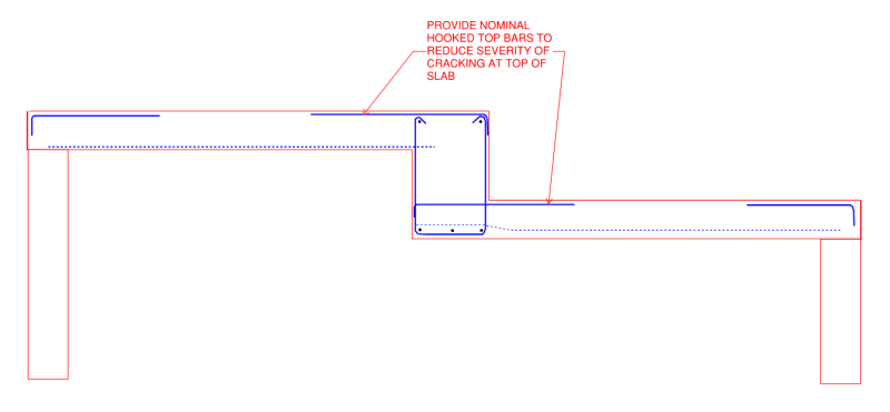
If you don't want the moment to be continuous across the beam, you can add a slab line release at the beam face (I assume you're using an FEA software similar to CSI's SAFE).
In this situation you'd typically provide nominal top bars with standard hooks to reduce cracking at the top of the beam but otherwise assume that there is no significant negative moment at the beam faces.
The additional benefit here is not having to design the beam for torsion (i.e. open stirrups)

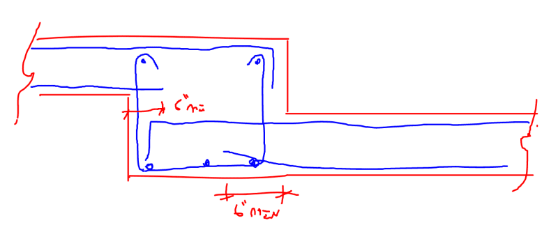
If you want to design for a moment, the top and bottom reinforcement should be bent through the fold in such a way that forces can be transferred across the joint & development length requirements are satisfied. I typically see them detailed like in my attached sketch. This is typically cumbersome to provide when beam stirrups & reinforcement are in place.
 
 https://files.engineering.com/getfile.aspx?folder=29bf8c6b-9237-409d-abe3-438f56429f8c&file=Moment_Across_Beam.PNG
Sometimes it makes more sense not to release the moments in the analysis, when there are big spans and the deflections would be a problem for example. It is this case I am trying to examine and try to see how would this be approached, whether by transferring the moment across the beam or treat it as rigid and therefore simply using straight (or simple hooks) for anchorage.

I will add two details, the first one uses hooks for the slab top reinforcement (say ∅12/10cm), while the beam stirrup is something less (say ∅10/15cm). The second one uses a closed stirrup that also acts as slab top reinforcement and the bottom part uses a hook - in both cases covering the full requirement (∅12/10cm).

Slab_step_-_Detail_2_s0wbbo.png

Slab_step_-_Detail_1_g4bqtu.png
 
If this is a suspended beam then I don't see how you can avoid enploying this detailing. Reality doesn't care about simplified model assumptions and pin detailing in a concrete beam is a dubious option at best
 
I prefer Z bars in couples, height of both full depth, extending horizontally to far face in each case. Do not turn any bars around an internal corner.
 
I would think that in your first option, the top bars (red) of upper slab would be hooked down into the beam unless it was perhaps really wide to develop by the beam-slab joint. Similar but mirrored detailing for the bottom bars (green).

*I don't do much concrete detailing, so happy to hear from anyone confirming/correcting this*
 
OP said:
...beam acts as a support therefore the moments in the slab will be negative requiring top reinforcement.

That may be the case but is by no means a given in my opinion. To be a "beam" in a meaningful sense, the beam thing needs to span to a source of stiff vertical support. In my experience, that's not true at many steps in which case the steps really serve only to create flexural continuity in the slab across the elevation change.

 
KootK said:
That may be the case but is by no means a given in my opinion. To be a "beam" in a meaningful sense, the beam thing needs to span to a source of stiff vertical support. In my experience, that's not true at many steps in which case the steps really serve only to create flexural continuity in the slab across the elevation change.

Yes, this is what I am trying to differentiate since the original post. By saying "beam" it is presupposed that it is an element sufficiently supported so that it can in turn support the slab. By saying "simple slab offset/ step" I mean a step that occurs in the midst of a slab without the ability to support it.

And the question is, does one have to guarantee transfer of moments across a "beam" in the same way that one has to do it across a "simple slab step"? Or could you simply anchor the required top reinforcement inside a sufficiently rigid beam and call it a day (picture 1 of original post)?
 
christar said:
Or could you simply anchor the required top reinforcement inside a sufficiently rigid beam and call it a day (picture 1 of original post)?

That one and, for that case, I would refer you to dijonnaise's comment above.

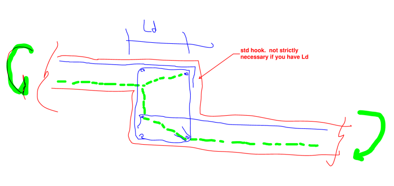
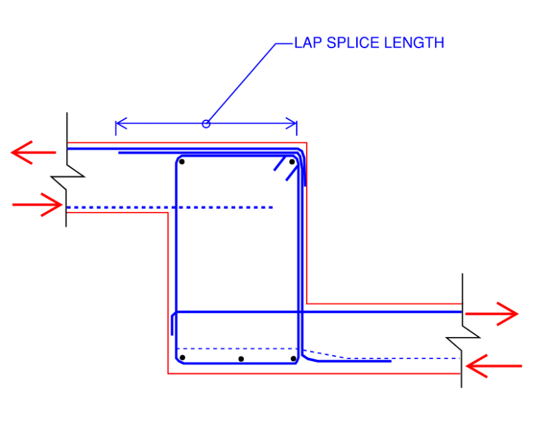
In this situation in my market (North America) I would consider the detailing shown below to be conventional, economical, and structurally adequate. You know, the "big three".

C01_kevwdb.png
 
Koot, in your stirrup you have no horizontal leg on the stirrup
Isn't this required to complete the strut and tie for a torsional concrete beam? Is the theory that the hooked bar at the top provides this?
If so, isn't that of pretty marginal benefit compared to just completing the stirrup cage?
 
GreenAC said:
Isn't this required to complete the strut and tie for a torsional concrete beam?

Ostensibly, the beam has no torsion. It's rectified by the rotational restraint provided by the adjacent slabs. Obviously, unless the moments are balanced on either side of the beam, there will be some torsion. It will, however, be self limiting.

GreenAC said:
Is the theory that the hooked bar at the top provides this?

I do see it as doing that job in a somewhat non-rigorous and non-explicit fashion.

GreenAC said:
If so, isn't that of pretty marginal benefit compared to just completing the stirrup cage?

It is marginal but, then, in the world of business, the margins are precisely where profits are earned. Moreover, my drawings will get compared to my local competitors who will avail their clients of these marginal benefits.

I believe that I do understand your NZ perspective to a large degree. Practice in NZ is so dominated by seismic concerns that there's basically no such thing as an open stirrup or tie and most hooks are 135. I'd do that too if this were a moment frame beam in Vancouver or Los Angeles. For gravity beams in more relaxed seismic jurisdictions, however, the open stirrups have been used successfully on a huge proportion of the building stock for over a century.
 
Kootk,

Most design codes would suggest you do not have 100% capacity of the top reinforcement at the corner where the stirrup and top bar "lap"!
 
rapt said:
Most design codes would suggest you do not have 100% capacity of the top reinforcement at the corner where the stirrup and top bar "lap"!

Good thing I'm only seeking 0% capacity there. There was no intention to lap the top bar and the right stirrup leg. I was sketching the true "beam" version of this rather than the "slab continuity" version.
 
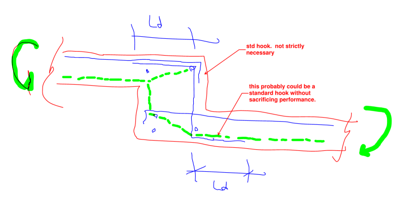
For sport, this is what I prefer for a continuity step. I believe that it is consistent with Hokie66's comment. Note that I've deliberately only shown the hogging moment rebar for clarity. Normally, folks detail it for both hogging moments and sagging moments concurrently. In that case, you wind up with another z-bar.

I don't consider this the most theoretically correct detail but, rather, the "market appropriate' detail which many would term "practical".

c01_v1hxqs.png
 
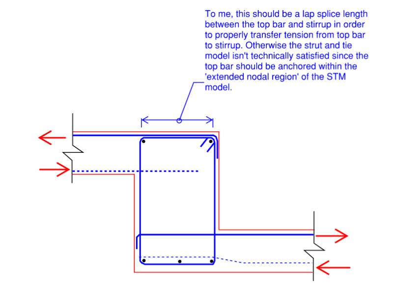
This is what I would consider the Cadillac version of the continuity detail, including closed stirrups. As can be seen, it's not so different from the previous version in the ways that matter.

c01_inxq1l.png
 
Does it make sense to treat the step as flexural member to find the tensile force acting on the vertical leg (where depth = beam width) or is this force equal to the tension coming from the slabs?

In Germany that we base all our projects on, the proposed detail for a step with required continuity is the 2nd picture in the OP for small steps and the 2nd picture in my next post for larger steps. The Z bar details that seem more popular in your regions do the job, although one could argue about bar placement difficulties on site.
 
chritsar said:
Does it make sense to treat the step as flexural member to find the tensile force acting on the vertical leg (where depth = beam width) or is this force equal to the tension coming from the slabs?

Typically, the vertical leg will be sized to match the top bars (note that if this is for a beam seeing shear in-and-out of the page that you should be providing additional stirrups for this moment transfer mechanism in order to not over-utilize the stirrups designed for beam shear).

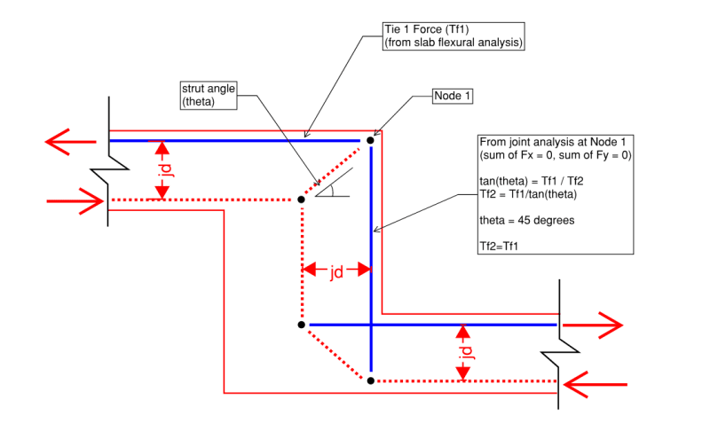
It does not 'strictly' make sense to think of this as a flexural member since this would be considered a discontinuous "D-Region" that should be analyzed via strut and tie methodology.

That said... the construction of the strut and tie model ends up being simplified by assuming that your vertical strut and tie likely only need to be as far apart as the horizontal struts and ties because using 45 degree struts resolved in equal horizontal and vertical tie forces, see below snapshot:

Strut_and_tie_beam_step_ek72bs.png

Edit: You could reduce the demand on the vertical leg by making the strut and tie model wider through the beam however if you're the vertical bar with top bar you'll want those sizes to match.

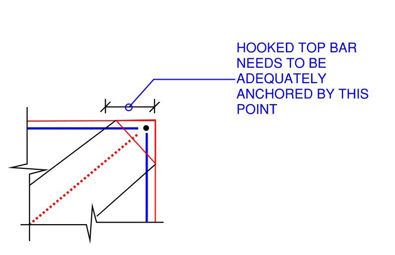
My only qualm with Kootk's "Cadillac" version of the detail is that to me the hooked bar at the top may not strictly be anchored to Node 1...

Cadillac_ofi07d.png

Top_Node_nngl9e.png


If you can't achieve that lap splice between top bar and stirrup I would tend to prefer the Z-bar detail lap-spliced with the top bar.
Slab_Fold_beam_gkhh4m.png

Obviously this becomes a bit of a congested situation which is exactly why I typically would not want to design my slabs to transfer moment across the beams, and instead make the pinned assumption at beam face and increase my positive reinforcement in the adjacent spans to suit flexural/deflection requirements.
Pinned_Beam_u4pyjp.png
 
OP said:
Does it make sense to treat the step as flexural member to find the tensile force acting on the vertical leg (where depth = beam width) or is this force equal to the tension coming from the slabs.

I would say that the tensile force would be somewhere between those extremes:

1) Reducing this tension force from the slab flexural values is one of the main reasons that we proportion the step as we do (w = 2h etc).

2) As dijon intimated, this will be a disturbed region so the flexural depth (width) will be less than the full width less a compression block. I usually take the lever arm at 0.7 x width for this purpose, paying homage to the park and paulay reduced lever arm method of deep beam design from the 70's.

3) The vertical stirrup legs will also need to transfer vertical shear from the low side to the top of the beam. This will create a continuous "hanger" situation that will add a bit to the stirrup demand relative to that predicted by straight beam shear concerns alone.

OP said:
although one could argue about bar placement difficulties on site.

This wouldn't be much of an argument in my markets (or vice versa). I can't even get 180 hooks because people hate feeding them through the bars that would run out of the page in these details. Your "C" and "Q" shaped bars would be mechanically awesome as a finished product but, from a constructability standpoint, they'd probably get me strung up form a tall tree with a short rope.
 
Status
Not open for further replies.

Part and Inventory Search

Sponsor