TopPocket
Mechanical
- Feb 16, 2022
- 50
Hi,
So I've found one of those "sounds simple at first" problems.
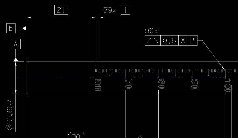
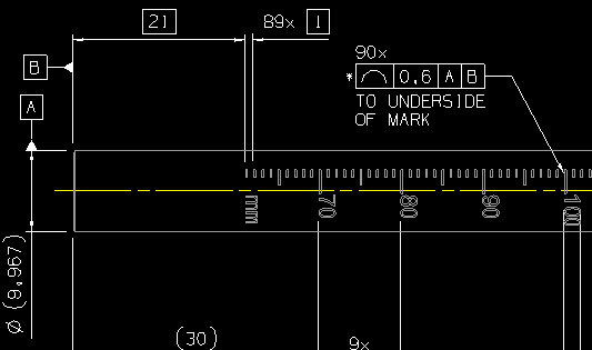
I have a part with a laser marked scale, imagine a glorified ruler.
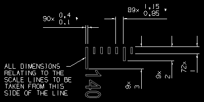
I need to specify the tolerance of the laser marks, specifically three things:
- Absolute position of each mark from end face
- Line Spacing between adjacent marks
- Thickness of each mark
Now the standard method would obviously result in an absolute mess, as the scale is 140 mm long (1 mm increments).
Is there a better way?
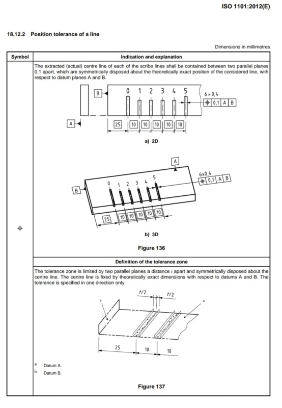
I've considered using position and TEDs but I think it is unclear. The most important thing is the absolute position of each line from the end face, so this is what I wish to be inspected, not a bunch of 1 mm increments.
There's ordinate dimensioning but I don't know how that works (oh I'm ISO btw, spice it up a bit).
I feel like there should be a way to start speccing them from the end face and do a kind of "..." ?
Any help would be appriciated.
Here's a pic for reference:


