Continue to Site

Eng-Tips is the largest engineering community on the Internet

Intelligent Work Forums for Engineering Professionals

  • Congratulations KootK on being selected by the Eng-Tips community for having the most helpful posts in the forums last week. Way to Go!

Eccentric load on weld groups 2

Status
Not open for further replies.

HanStrulo

Civil/Environmental
Apr 16, 2021
117
HI Everyone,

For anyone familiar with both AISC and CISC. I have a question.

Table 8-4 of AISC gives the coefficient C for eccentrically loaded weld groups (out of plan force and at an angle of 45 degrees).

I looked in CISC and could not find a similar table. The closest i could find was table 3-27 but it's for in-plan eccentric vertical load).

Did i miss something? what is recommended to do in this case?

Thanks
 
Replies continue below

Recommended for you

Without cracking a book to verify, I believe that:

1) Either the weld group tables are non-dimensional OR;

2) The weld group tables can easily be made non-dimensional.

So you can pretty much just use whichever tables you find to be a better fit for your problem, regardless of whether their AISC or CISC. The weld group stuff is primarily a geometric parameter and, thus, agnostic to the geographic location of the designer / project.
 
CISC is more restrictive and limits the C coefficients to loads acting parallel to the weld group. For inclined loads, the AISC is the way to go. Table 3-27 was primarily intended for in-plane loading. For out-of-plane loading, Table 3-34 was provided, but again is restricted for loads acting parallel to the weld group.

To comment on KootK's remark, the C coefficients are not dimensionless parameters. The C coefficents represent the equivalent weld stress resultant from a force acting at a set eccentricity from the weld group's center of gravity. They are therefore dependent on the strength of the electrode applied (AISC = 70ksi; CISC = 490MPa ~ 71ksi). You can convert AISC C coefficients to an equivalent CISC C coefficient by dividing the AISC C coefficient by 12 (this is a result of how each manual communicates the values using the weld size; the AISC which applies the weld size in the number of 1/16" the weld is comprised of (e.g. 5/16" fillet equates to 5 x 1/16, therefore D=5 for AISC method) and CISC which uses the leg size for D (e.g. 5/16" fillet is equated to a 8mm fillet, therefore D=8). The conversion factor of 12 results from 0.75 x 16 (0.75 being the phi factor, and 16 coming from the AISC weld size definition). This conversion factor does assume that the same electrode is applied across each manual, so take that into consideration if applying this conversion factor.

For out-of-plane loading using the AISC manual, you should be cautious as to its use. I believe the design tables implicitly assume that the connection material is rigid enough to develop the full weld strength. In certain framing conditions, this may not be the case. For a prime example, consider a double angle connection welded along its toes to the support (a pretty typically framing case) and subject to an axial load and a vertical shear at some eccentricity. The AISC tables may appear suitable, but research has shown the welds prematurely fail due to the angles being too flexible; additional stresses build in the welds as the angles rotate and cause bending/tension at the root of the welds. A case where the AISC tables for out-of-plane loading would be suitable would be a HSS outrigger with 2 parallel welds to the support subject to an axial load and a vertical shear at some eccentricity.
 
MGaMart said:
To comment on KootK's remark, the C coefficients are not dimensionless parameters.

They can be made non-dimensional by dividing out by the unit resistance of the weld etc, in a manner nearly identical to what you did in the conversion in your second paragraph above.

KootK said:
2) The weld group tables can easily be made non-dimensional.

I still contend that the weld group tables are fundamentally about the geometric parameters alone, at least for a given load-deformation relationship. That particular loads and weld sizes can be used in the tables is just an extra layer added for convenience sake.
 
It's not clear to me why you would want to apply that additional step in an attempt to make it dimensionless. The top of each table (in both manuals) clarifies the C coefficient by providing the formula for arriving at the weld group capacity, which defines the (required) coefficient C as the ratio of the required load Pu to the product of weld size and weld length (i.e. force/area) which results in a required stress. The AISC goes one step beyond the CISC and includes a C1 parameter which takes into account the electrode strength (Table 8-3) if you're are using weld other than the industry standard E70 (E70 I believe was also applied in the research performed that led to the development of the load-deformation relationship that these tables are based on, hence the C1 term for E70 was defined as 1.00 and all other electrodes were referenced relative to E70).

You're correct that the weld group tables are heavily reliant on the geometric parameters of the system, however the load-deformation relationship that is tied to the Instantaneous Centre of Rotation (ICR) method is a integral part of how these weld tables were calculated. Fortunately, the load-deformation relationship can be applied across a spectrum of weld sizes and lengths which provides greater utility to the designer.
 
Thanks for the clarifications.

I am welding a channel (C200x27) to a 400mm pipe and I did not do any additional checks for the stiffness of the system to be honest.

@MGaMart, table 3-34 looks like it was made for welding a plate since one of the parameters it is requiring is the plate thickness and it only goes to 40mm spacing between the welds. is my understanding correct? Could it be used for anything else?

Edit: just adding that I used the AISC table and got the weld size i needed from it and then multiplied the size by the factor 0.75/0.65 to convert it which is i believe identical to your conversion of 16*0.75 applied directly to C. Thanks for the tips.
 
MGaMart said:
It's not clear to me why you would want to apply that additional step in an attempt to make it dimensionless.

I'm not actually recommending that anyone should do that. Rather, I'm using the fundamental, non-dimensional characteristic of the tables as a logical argument to justify the use of either the CISC or the AISC tables so long as that is done intelligently. My point is simply that the core nature of these tables is utterly agnostic with regard to which standard one is using (AISC vs CISC).

MGaMart said:
You're correct that the weld group tables are heavily reliant on the geometric parameters of the system, however the load-deformation relationship that is tied to the Instantaneous Centre of Rotation (ICR) method is a integral part of how these weld tables were calculated.

Yes, and I believe that I myself mentioned that very thing in my previous post.

KootK said:
...at least for a given load-deformation relationship.

But, then, as anyone familiar with both standards knows, AISC and CISC treat the load-deformation relationship identically so it boils down to just geometry like I said.

 
HanStrulo said:
I am welding a channel (C200x27) to a 400mm pipe and I did not do any additional checks for the stiffness of the system to be honest.

In practice, detailed stiffness checks are rare and judgement predominates.

Will you weld the flanges to the pipe as well as the web?

Is the web oriented parallel to the pipe or perpendicular to it?

 
You know, a sketch would be great here...
 
Only the channel webs will be welded to the pipe for a length of 500 mm to reach capacity.

channel_ywoo9a.png
 
Welding the toes of the flange to the pipe?... definitely not what I imagined was the framing scenario. To respond to the Table 3-34 comment, it is quite restrictive in its application and I hardly ever refer to it in practice. In your scenario, you would be better served to apply the AISC manual Table 8-4 and take K=0 (as mentioned at the top of the table for out-of-plane loading). If this is a heavily loaded channel, you may want to consider swapping the fillet welds for complete joint penetrations, whether that be bevel grooves or square grooves with backing. I'm never fond of seeing that large of an obtuse angle in laying down a fillet weld. A CJP weld may prove the easier route and eliminate any possibility of weld bending (however small of a concern given this specific framing condition).
 
Is the load vertical (transverse to pipe) in your sketch or in and out of the page (parallel to pipe)?
 
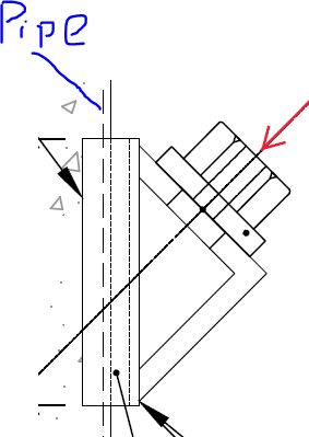
the load is out of page. This is part of an anchor connection. basically strand cables are supported by an angle (203x203x25) at 45 degres which is in turn supported by the channel you see in the drawing which is in turn supported by the pipe. this is apparently a standard practice but my first time checking one.
 
Any chance you could expand your sketch to show how the angles frame into the channel? If a 203x203x25 angle is being applied, that raises concerns beyond the weld design which should also be addressed. I'm thinking primarily pipe wall stability (i.e. plastification) and depending how the angle frame to the channel, possibly channel web plastification.
 
I might simplify things by just saying that all of the moment and direct tension is transferred over the upper and lower 1/6th of the channel. Add that demand to a uniform shear and just apply that everywhere unless it comes out nutso. And there's nothing rigorous about the 1/6th, just an acknowledgement of the uneven weld stresses likely to develop.

In some applications, AISC directs you to multiply demand by 1.25 to compensate for non-uninform stiffness. I'm not sure that would apply here though. This doesn't strike me as the kind of problem that one wants to run a detailed FEM model for.
 
I have included a larger image below.

Pipe_jom5d3.png


As you can see, that is the load at 45 degrees and the channel weld i am checking.
 
It seems to me that your channel to pipe welds here would only have to transmit shear then. The compression would be by direct bearing and there probably wouldn't be any net flexural tension on the welds. Of course, some folks feel that, even in this situation, the welds ought to be designed for that compression. That would steer me back to the 1/6th business again.
 
The plot thickens.... With this new information, the eccentric weld tables may not be the best approach to this design. So long as all the elements leading up to the welds to the pipe have sufficient flexural/shear capacity to transfer the force to the next element, AND so long as the pipe weld group center of gravity is collinear with the line of action of the strand cable force, the welds at the pipe could be designed simply as a inclined load without eccentricity considered. Unclear how long the angle is, i.e. does it at least extend across the depth of the channel, flange-to-flange? If not, the channel web plastification I mentioned may govern the design. The 25 thick angle is now making much more sense. Even though the force vector shown suggests compression, you did mention it was a cable, so I assume this framing condition may be subject to tension force? The channel should ideally extend well beyond the toes of the angles (sketch provided I assume isn't to scale), otherwise an end plate/stiffener on the channel that's also welded to the pipe would be recommended. What kind of forces are you dealing with? As KootK correctly mentioned, if compression only, shear parallel to the pipe may only be required for weld design, but designing the welds to also develop the force perpendicular to the pipe is recommended if proper contact bearing cannot be guaranteed.
 
MGaMart said:
The channel should ideally extend well beyond the toes of the angles...

I had the same thought and definitely second that.
 
Load appears to be at the mid point of the channel... I'd design it for the horizontal and vertical components on the channel weld to the 'pipe' and combine horizontal and vertical shear stresses. Only moment is from the vertical shear acting through the depth of the channel.

Rather than think climate change and the corona virus as science, think of it as the wrath of God. Feel any better?

-Dik
 
Status
Not open for further replies.

Part and Inventory Search

Sponsor