Eng-Tips is the largest engineering community on the Internet

Intelligent Work Forums for Engineering Professionals

Ferry Dock Collapse 9

dik

Structural
Apr 13, 2001
25,560
0
36
CA
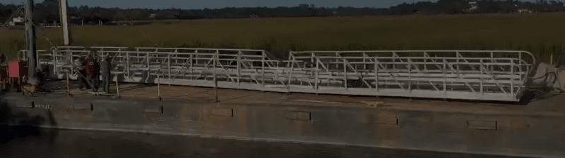
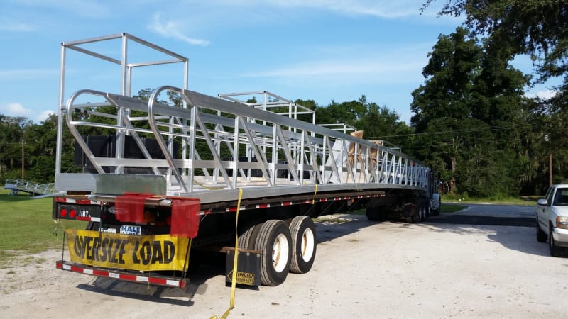
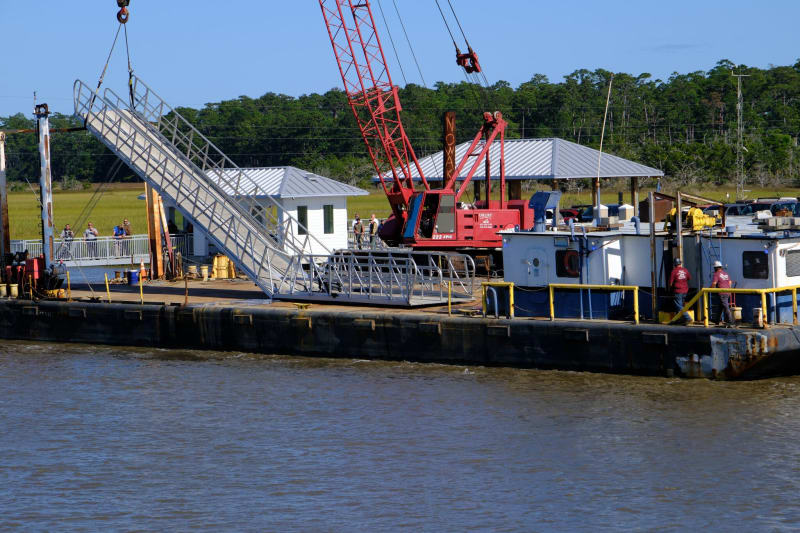
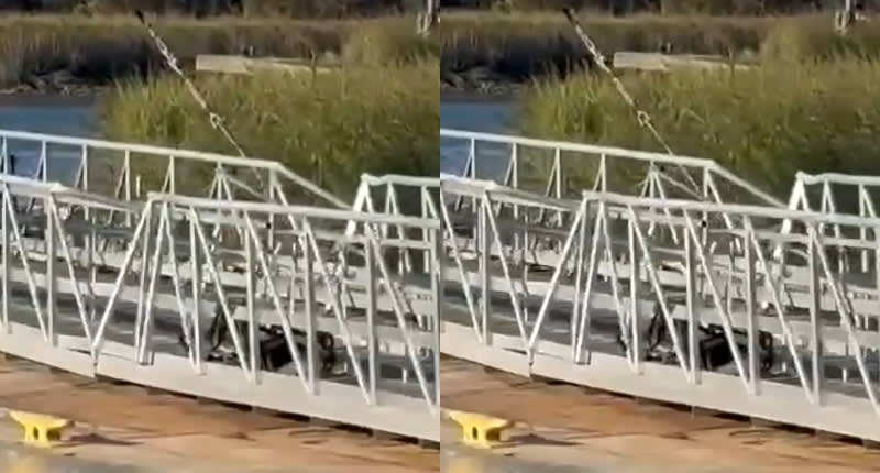
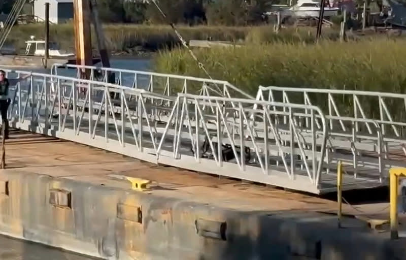
"At least seven people were killed and several others injured Saturday after part of a ferry dock collapsed on Georgia’s Sapelo Island, according to the Georgia Department of Natural Resources.

It happened as crowds gathered on the island for a celebration of its tiny Gullah-Geechee community of Black slave descendants.

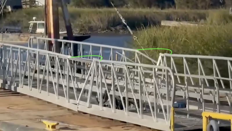
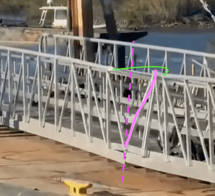
At least 20 people were plunged into the water when a gangway collapsed on the visitor ferry dock shortly before 4 p.m., Georgia DNR Capt. Chris Hodge said at a Saturday night news conference. A McIntosh County commissioner previously said a boat hit the dock but a DNR spokesperson later told The Associated Press there was no collision and it is unclear why the dock collapsed."


-----*****-----
So strange to see the singularity approaching while the entire planet is rapidly turning into a hellscape. -John Coates

-Dik
 
Replies continue below

Recommended for you

Given the failure seems to have occurred 2/3 the way along is it feasible the just welded on ana extra 20ft or so to a "standard" 60ft gangway?

That main beam failure looks too "neat" to be a beam failure but looks more like a weld failure to me.

Remember - More details = better answers
Also: If you get a response it's polite to respond to it.
 
Actually looks more like half way.

Screenshot_2024-10-21_145835_y8h9ca.png


Remember - More details = better answers
Also: If you get a response it's polite to respond to it.
 
Failure to consider loss of strength in the weld affected zone? Seems like too many engineers go into aluminum design without understanding the material, assume it's like steel with a lower yield stress, and just pick sizes.
 
All of the ferries around here (there are a lot) discharge arriving passengers and vehicles first, only then allowing additional passengers and vehicles to board. All traffic is oneway.

--Einstein gave the same test to students every year. When asked why he would do something like that, "Because the answers had changed."
 
Maybe this was as well, but this was a special weekend with lots more visitors than normal so maybe they did wait on the main dock and were all just going down the ramp to the boat dock or queuing waiting for the others to get off, just the gangway had never seen so many people before now.

Everything is telling me that this was a modification / extension of their "standard" pre fabricated 60 ft longest largest gangway and they just added an extra length or stuck two 40ft ones together somewhere after transporting them as two sections.

Remember - More details = better answers
Also: If you get a response it's polite to respond to it.
 
Given it was a special weekend, I'm surprised that none of the people there were shooting videos at the time, or if they were, none seems to have made it to the web. You'd think in something like this, what with everyone having a smartphone and people's penchant to video everything these days, why haven't we seen anything? Or haven't we really looked for anything yet?

John R. Baker, P.E. (ret)
Irvine, CA
Siemens PLM:

The secret of life is not finding someone to live with
It's finding someone you can't live without
 
Bugbus,

Please don’t stop your ramblings. I’m curious, what happens when you change the following parameters in your model?:

Cross girders from 6x3 to 2x1 1/2
3x3 top chord to 3” pipe
165lbs/person to 200lbs.

Also, what is the natural period of this thing?
 
The bottom beam looks like it is a box section with a plate welded tot the inside edge which the truss members are then welded to.

So a bit like a "d" shape. Hence you can see the tear between the thin upward section and the main box beam. So nothing like their standard gangway design Sym P Le posted earlier.

All very odd.

Who is doing the investigation? Local Georgia state or NTSB? (As it's transportation related)

Remember - More details = better answers
Also: If you get a response it's polite to respond to it.
 
The torn thin plate atop the hollow section may be an additional rub plate as it obviously has no structural purpose. It looks like a number of clean tears occurred at butt weld connections.
 
That looks like a toe kick to me. The drawing for the 60’ gangway uses the bottom chord as the toe kick, which only allows room for a 2” deep cross member. The separate toe kick we see here is a better design.
 
The design along the dashed pink line supports earlier comments about a standard 20' design was married to a standard 60' design.

1. Scrub plate is welded near 2/3 point of span thus not at center line.

2. The diagonals are in opposite direction and form a V at that point, with no vertical from bottom of V to top rail.


Screenshot_2024-10-21_at_10.02.31_AM_snlweq_oretgu.png
 
The V is an optical illusion. The reversal does happen where the opposing diagonals meet at the top rail. See the full side view above and the V disappears.
 
The vertical is there, it moved.
Screenshot_2024-10-22_094348_texa4q.png


"In general" a semi-trailer box or flatbed is 53 feet max. That limits the length of the extrusions that Crescent likely uses.

As phamENG noted, maybe they didn't consider the loss of strength when they decided to weld extrusions together to make a long bottom.

Maybe they were bad welds.

Maybe both.

Anyway, the "magic design" that works for any length, and width and any loading seems to have a limit.
 
If you dig back far enough you can find evidence that at some point somebody recognised the need for proper lateral restraint of the top chord...
460989773_3260886487380002_4308689499697102859_n.jpg_dz4gwt.jpg


And in other cases beefing up the top chord:
462466791_3276595572475760_6680087092804503063_n.jpg_thlzqa.jpg


But clearly somewhere along the line they decided that proper engineering was too costly...
 
It's rather difficult to differentiate damage sustained during recovery from that of the collapse however I derived a cross eye 3D view from the above posted video link in case it helps to understand the current state of the structure. Note that the damage on either side does not occur at the same truss section. I also notice that the cross ribs supporting the walkway protrude beneath the side rails so they are deeper than the brochure drawing indicates.

3D.snapshot.03_zfpcwq.jpg


2D.snapshot.03_n6fqx6.jpg
 
I regret that I can give but one star Sym P. le, 3D for the win.

At the least it would appear that the places that have no damage were not part of the initial failure.
 
I really hope they didn't break it getting it on the barge and actually did some dive surveys.

But indeed if this was at low tide as apparently it was, then it might not have taken much of a bending to have the far end drop off the pontoon deck. Then the subsequent fall and the thing hitting the bottom could have bent it more.

Interesting that many of the longer gangways appear slightly bowed in their neutral position but this one has always looked very straight.

but I do hope they didn't just drag it out of the sea one end at a time... I can't see any other wires on the far end.


Remember - More details = better answers
Also: If you get a response it's polite to respond to it.
 
Back
Top