Continue to Site

Eng-Tips is the largest engineering community on the Internet

Intelligent Work Forums for Engineering Professionals

  • Congratulations KootK on being selected by the Eng-Tips community for having the most helpful posts in the forums last week. Way to Go!

FREE BODY DIAGRAM 1

Status
Not open for further replies.

elinah34

Mechanical
Aug 19, 2014
115
Hey,
I have a conceptual design, and I need to first check its potential strength.
Here is a schematic picture of the conceptual design:
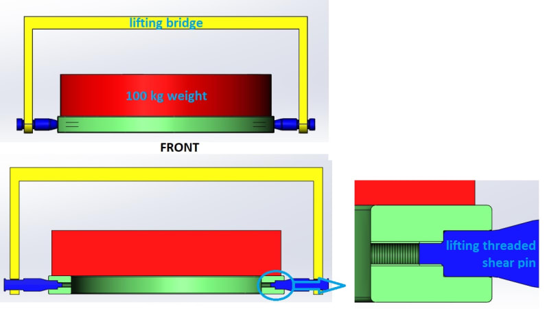
1_kub7g4.jpg

I have a lifting bridge for lifting the weight through its interface which has 2 Shear pins for taking the shear.
The Shaft/Hole fit (marked in purple in the picture below) is H7/g6, so there is a transition fit.
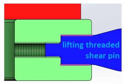
2_sqayc4.jpg

By the way, the thread is loose while the Shaft/Hole fit is tight, so theoretically the Shaft/Hole interface is the one to take the loads due to bending and not the thread, which is there only to axially secure the threaded pin in its place.
I tried to have a FBD (Free Body Diagram) of the threaded pin part, which I suppose is the critical one.
Here is a picture of my FBD:
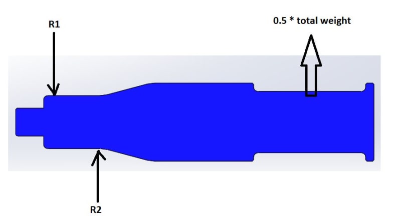
3_y7ai4g.jpg

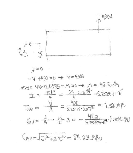
Here I try to find the internal (in the critical cut) forces and moments by equilibrium:
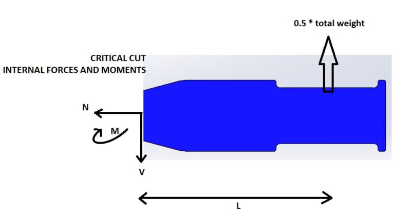
4_gfm8rd.jpg

After finding V and M I find the shear stress and the normal stress using V/A and (M/I)*R correspondingly, and using von mizes relation sqrt(sigma^2 +3*tau^2) brings me to 80 Mpa.

The problem is that in the analysis I get around 25 Mpa.
I have to point out that I already checked a configuration in which there isn't a thread at all (as in the picture below), and the results didn't change.
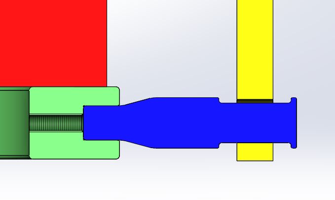
5_yaihkp.jpg

So I am interested to know which one might be mistaken - the calculation or the analysis?
I just hope you can help me by checking the calculation process I made.

Thanks
 
Replies continue below

Recommended for you

Thanks, I get it now 😀👍

“Do not worry about your problems with mathematics, I assure you mine are far greater.” Albert Einstein
 
The index plunger doesn't stop the torque arm from rotating away from the bridge frame. If the load is high enough the ring will twist taking the pivot pin with it and move the torque arm out of engagement with the index plunger.
 
@3DDave - one assumes that the ring is designed with sufficient stiffness to prevent a second order failure of that kind. Given the load is a whopping 100 kg total, it's an entirely plausible design.
 
"one assumes" isn't good engineering practice when "The motivation is making sure that improper use of the device may not immediately lead to a failure." which may mean this gets snagged and the load is 10,000N.
 
Hey
rather_be_riding the bushing is for preventing cold welding of the metals (PH 15-5/AL 6061-T6).I think there is a little chance it may happen, but I don't want to take a chance.

3D Dave, the carried load CG is almost coincide with the ring symmetry axis, so the plunger is expected to endure a small shear force.
 
Does the pin thread into the ring?

You don't answer questions, but then question answers?
 
@3dDave

I don't think the remainder of the design was really the OPs question. They were specifically asking about the analysis of the pin.

If we really want to get into misuse cases, the only real solution is load limiting on the hoisting device. If this happens to be sitting under a 50 tonne crane for example, there's no reasonable way you're going to protect against all modes of load snag. The practical outcome in most facilities is just that operators have to not be zombies because SOMETHING somewhere has to fail if you snag. If it's not the lifting device, it'll be the hoist or the unfortunate item that gets snagged. Load limiting tends to be impractical for any system that hoists more than one load of course which is almost always the case where we see lifting points intended to be used with hooks (as this one is). If I want to limit the crane to match a lifting device, it's usually permanently close coupled without a hook.

If the OP is working to a lot of common standards, they probably have a factor of safety of 2 in that 100 kg load already. A lot of lifting devices are tested at twice the rated capacity prior to commissioning.
 
@rather - the OP has skipped answering a number of questions. I doubt that you have any answers.
 
OP ... please explain this comment in the OP ...
"The problem is that in the analysis I get around 25 Mpa."

Your analysis looks to be theoretically reasonable, but the design seems to have real world issues (mostly the very minimal support of the load).
Now, maybe there are good reasons for this, but we don't know your design decisions and limitations that led to this design.

You ask about your FBD. Sure, that is a solution, a fairly reasonable solution if a lot of assumptions are made. The question I think we have is does the FBD accurately reflect your specific design, given we can't see all of the design. And are you accepting of the (implicit) conservatisms within the FBD, or are you looking for something more accurate.

Are you saying that your hand calc gives 80MPa but an FEA gives you 25MPa ? Not very surprising if this is the case.

another day in paradise, or is paradise one day closer ?
 
Sorry for the delay in replying.
I don't have access to the computer most of the week, and it's very difficult to answer in detail through my mobile phone.

3DDave
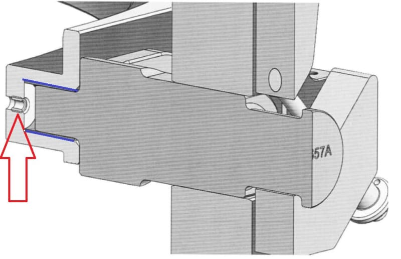
"The thread is shown in bending, unlike the original problem statement; not an ideal condition as it creates a stress concentration, possibly 5 to 10 times the expected stress" - which thread do you mean? maybe you think the blue interface in the picture below is a thread? if you do, so it's not, it's just H7/g6 fit od the pin to the bushing. if you meant the thread that is marked with an arrow, so nothing is threaded into it at this stage.
1_huaxjd.jpg


"It looks to me like this arrangement will twist the ring and then the pin will sit at a substantial angle in the cradle" - why? 2 is secured to 1 through the bolts that aren't seen in this section view, 3 is secured to 2, and 5 locks 3 and located at 4. as a result there will be only negligible movement due to small clearances of mating surfaces.

"Does the pin thread into the ring?" - no, see my explanation above.

rather_be_riding
"external fasteners fail to hold that joint tight" - why? if they generage axial loads that lead to enough friction (coefficient of friction*total axial force) the pin/hole interface isn't theoretically needed, but is there only for a backup.
In addition I agree that analyzing this problem like I did is very far away from reality, but I should prove this device for the worst case scenario in which no bolts are tightened and no face to face tightening exists, and as a result all the load is carried by the pin.

A new update - After reviewing my analysis with an expert we found a problem in some contacts in the analysis, something that led to distorted results, and after fixing it the results were quite close (+/- 10%) to the hand calc!!!
 
@elinah - I wasn't suggesting they wouldn't hold the joint tight; I more meant a fail safe in the event someone fails to tension them properly. We're in agreement. Glad your check matched up in the end.
 
Elinah34,

I suggest you reconsider your design if you have not done so. The lifting mass centre of gravity point should always lover than the handling shaft centreline. Otherwise there will always be a tendency of failure in the balance of lifting mass and lifting equipment. This should be a major point in the risk analysis for the entire lifting operation.

This may probably change your design slightly or substantially, you need to decide.
 
saplanti, you are right.
As I mentioned earlier, you see only partial image of the entire assembly. In the reality the c.g should coincide with the axis of rotation.
 
Dear elinah34 ,

I did not read the previous posts but just screened. The FBD at your 4th post is OK but there are some errors at calculation . ..

6_ko18di_g82dp1.jpg


I =( Π* R**4)/4 If D=18 mm r= 9 mm = 0.009 m.

I = ( Π* 0.009**4)/4=5.15 *E-09 or ( 5.15*10**(-9 )) M**4

σ = M*y/ I =( 48.2*0.009)/5.15*10**(-9) =84,233,009.71 N/m2 so, 84.2 MPa is OK.

The Von Misses stress calculation shall give the same result .

When you assume the section as a clock, the max bending stresses will develop at 6 and 12 hrs.
The max . shear stress will develop along the axis 9 to 3 .

So the max stress in this case at 6 and 12 aclock.

PS.
1- When you apply FS =4 , ( Common practice for lifting tools and eq.) that makes 337 MPa. what is the yield str. of the material?
2- I f i were, i would consider a different set up.( such as a cross piece lifting frame and four point lifting with cable etc )
 
as much as we look at the blue pins, we also should look at the yellow lifting beam in the 1st post.

another day in paradise, or is paradise one day closer ?
 
HTURKAK
Thanks for checking the calculation. There is a requirement of having the ability to rotate the lifted mass while it's lifted. That's why there is a 2 point (along an axis) connection.

rb1957
The yellow jig is an existing one that is proven to safely lift up to 300 kg mass.
 
I think the reason you're seeing such a discrepancy between your hand calculations and the FEA results are because you're using σ = M*y/ I to determine bending stress.

Beam bending is only really valid when the span/depth ratio is around 8 (according to Roark)... It appears you have a span/depth ratio less than 1 (L=17.1mm and D=18mm). As such your pin will not act like a beam.
 
_eh-ngineer
Thank you. Which formula is relevant for hand calculation in such cases ("short beam")?
 
Status
Not open for further replies.

Part and Inventory Search

Sponsor