elinah34
Mechanical
- Aug 19, 2014
- 149
Hey,
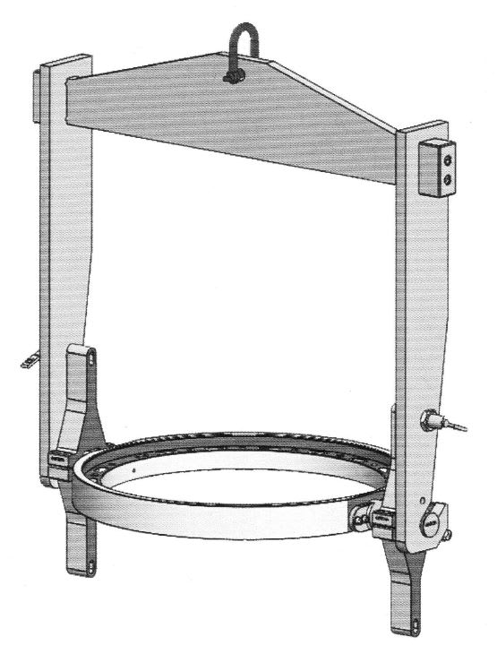
I have a conceptual design, and I need to first check its potential strength.
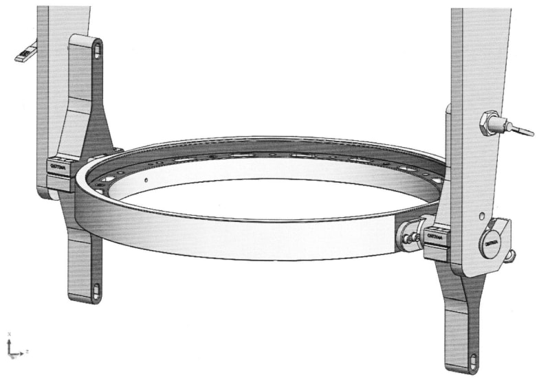
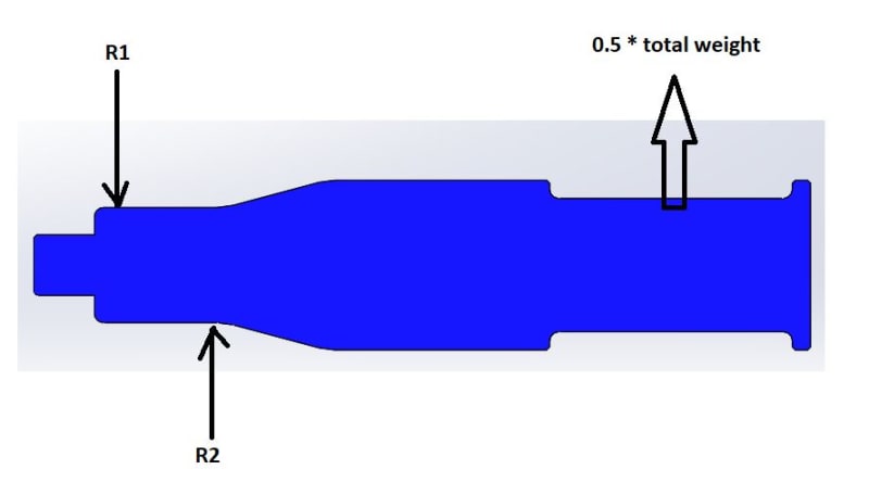
Here is a schematic picture of the conceptual design:
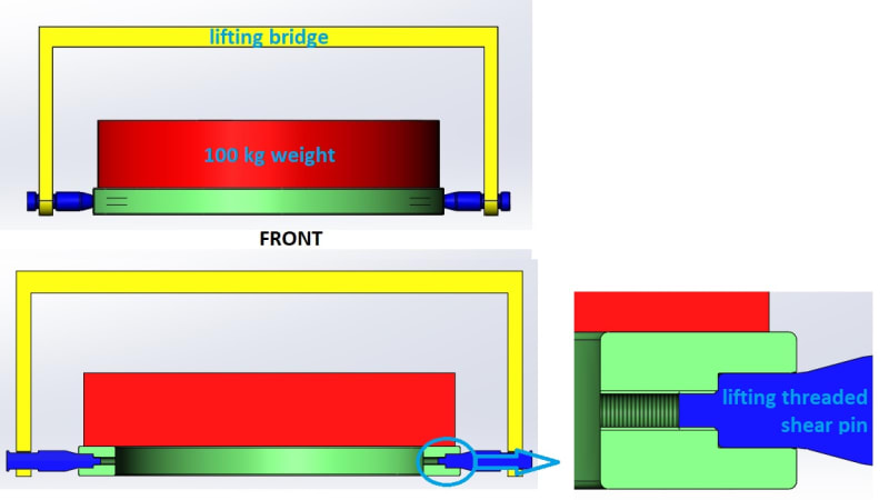
I have a lifting bridge for lifting the weight through its interface which has 2 Shear pins for taking the shear.
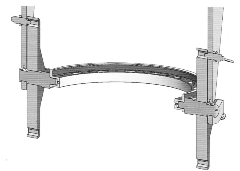
The Shaft/Hole fit (marked in purple in the picture below) is H7/g6, so there is a transition fit.
By the way, the thread is loose while the Shaft/Hole fit is tight, so theoretically the Shaft/Hole interface is the one to take the loads due to bending and not the thread, which is there only to axially secure the threaded pin in its place.
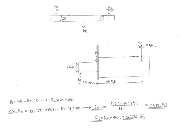
I tried to have a FBD (Free Body Diagram) of the threaded pin part, which I suppose is the critical one.
Here is a picture of my FBD:
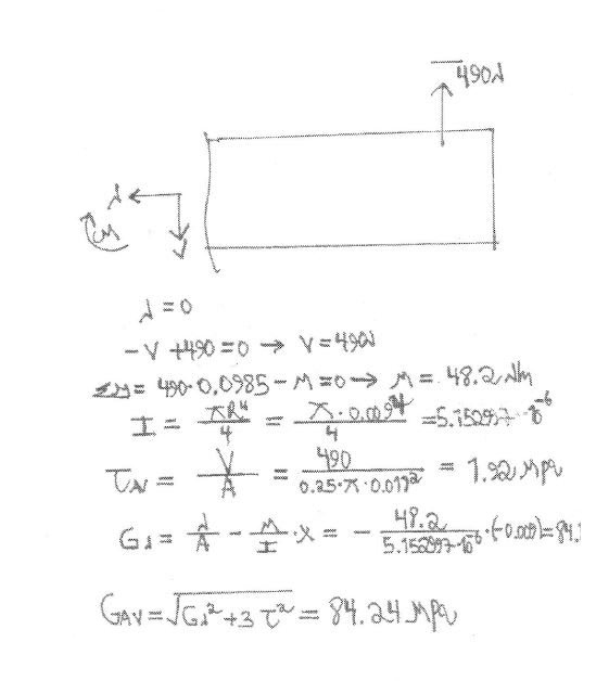
Here I try to find the internal (in the critical cut) forces and moments by equilibrium:
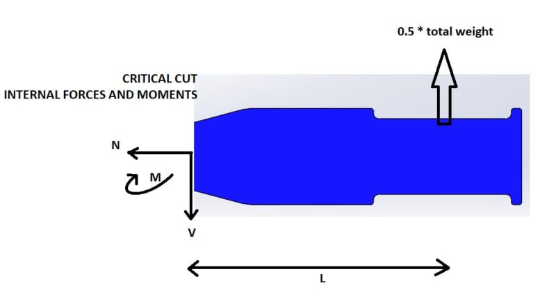
After finding V and M I find the shear stress and the normal stress using V/A and (M/I)*R correspondingly, and using von mizes relation sqrt(sigma^2 +3*tau^2) brings me to 80 Mpa.
The problem is that in the analysis I get around 25 Mpa.
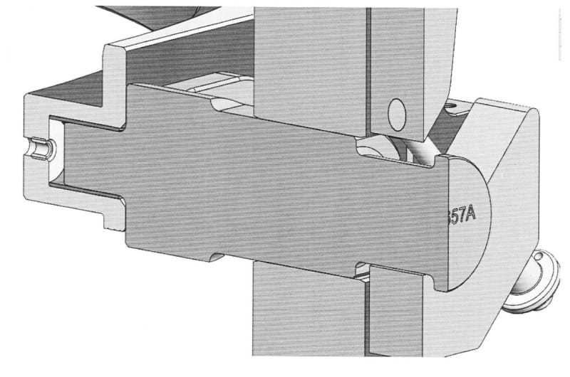
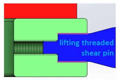
I have to point out that I already checked a configuration in which there isn't a thread at all (as in the picture below), and the results didn't change.
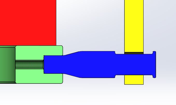
So I am interested to know which one might be mistaken - the calculation or the analysis?
I just hope you can help me by checking the calculation process I made.
Thanks
I have a conceptual design, and I need to first check its potential strength.
Here is a schematic picture of the conceptual design:
I have a lifting bridge for lifting the weight through its interface which has 2 Shear pins for taking the shear.
The Shaft/Hole fit (marked in purple in the picture below) is H7/g6, so there is a transition fit.
By the way, the thread is loose while the Shaft/Hole fit is tight, so theoretically the Shaft/Hole interface is the one to take the loads due to bending and not the thread, which is there only to axially secure the threaded pin in its place.
I tried to have a FBD (Free Body Diagram) of the threaded pin part, which I suppose is the critical one.
Here is a picture of my FBD:
Here I try to find the internal (in the critical cut) forces and moments by equilibrium:
After finding V and M I find the shear stress and the normal stress using V/A and (M/I)*R correspondingly, and using von mizes relation sqrt(sigma^2 +3*tau^2) brings me to 80 Mpa.
The problem is that in the analysis I get around 25 Mpa.
I have to point out that I already checked a configuration in which there isn't a thread at all (as in the picture below), and the results didn't change.
So I am interested to know which one might be mistaken - the calculation or the analysis?
I just hope you can help me by checking the calculation process I made.
Thanks