For stamped parts the twist and springback can vary, but you should have access to a stress analyst who can do the following:
1) Constrain the model to a few locations that would be used as target points
2) Run load cases with unit forces at each of the other target points - 5 free points, 5 load cases.
3) Measure the deflections at all the unconstrained target points for each load case.
Now for a little matrix math, your FEA guy should be able to help; if you have a local university math department give them a try - often math professors enjoy a small side-puzzle that makes real use of their ability.
This measurement set is the matrix of force to deflection. Inverting that matrix and multiplying by desired deflection will produce forces. This way you can see how much force it would take if there was one spot bumped up, or if many were twisted, from a simple spreadsheet.
If a similar analysis is applied to the finished assembly with the mating part, then the forces that will be trapped by assembly can be used to calculate how much the assembly will deflect once the fixturing is released.
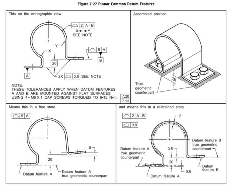
Simple example, no matrix - a rectangular strip of metal that will be held with 3 rivets, one at each end and one in the middle. Assume it is checked using datum targets where the rivets will be to constrain it.
The FEA (or one might use a simple beam formula) for a hinge at one end rivet, a roller at the other end rivet, and a small load where the third rivet will produce a deflection per that load. Typical load is a unit of 1; preferably a small unit so large deformation doesn't interfere. It's to flex the part, not plastically force it.
Then look at the same data for after all 3 rivets are in place with the mating plate.
Try a 10mm wide by 100mm long by 0.5 mm thick steel strap onto a 20 mm wide by 100mm long by 2mm thick plate and calculate the deflection from a unit load applied at the same middle rivet. Put the end rivets 10 mm from the end for this example.
Assume that a 1 centiNewton force causes the strap by itself to deflect 6mm. That means to flatten a 6mm gap at the middle rivet takes 1 centiNewton. Now apply the 1 centiNewton to the combined part at the middle rivet. It may produce a 1 mm bend. If the finished requirement is 0.5 mm, then you know that you need 0.5 centiNewtons of force and the first strap has be be made with less than 3mm of free state deflection.
Note: the deflection numbers above are incorrect. Finding the correct values is left to the student.
The example is simple enough to get some metal strap (caution of burrs) and do the steps. There will be some differences if the thin strap is left in the free state, it doesn't account for the leverage at the ends - give a try and you can see it happen, making the effect of the strap initial deflection count for less.
Unlike D&T trainers, I'm not paid to generate a book on this topic, which is something that ASME should have for sale as part of what I consider advanced topics in tolerance analysis. As a result I cannot get more detailed, but the FEA engineer, a helpful math professor, and the supply of metal pieces and some pop rivets, should be able to fill in the gaps to get an understanding.
See also for academic treatments
2007
2012
Either many users already know this or no one uses it - not much research being turned up.
![[bigglasses]](/data/assets/smilies/bigglasses.gif "[bigglasses] [bigglasses]")
![[bigsmile]](/data/assets/smilies/bigsmile.gif "[bigsmile] [bigsmile]") btw...it is clear your suggestion but i was wondering if there is a way to put in a drawing using the GD&T a procedure to make a check of the datum features once the part is put in the gauge but with the clamps opened to see, for example, how far the datum feature is from the pad of the datum feature simulator on the gauge...
btw...it is clear your suggestion but i was wondering if there is a way to put in a drawing using the GD&T a procedure to make a check of the datum features once the part is put in the gauge but with the clamps opened to see, for example, how far the datum feature is from the pad of the datum feature simulator on the gauge...![[wink]](/data/assets/smilies/wink.gif "[wink] [wink]")