Continue to Site

Eng-Tips is the largest engineering community on the Internet

Intelligent Work Forums for Engineering Professionals

  • Congratulations KootK on being selected by the Eng-Tips community for having the most helpful posts in the forums last week. Way to Go!

FREE STATE MODIFIER WITH DATUMS

Status
Not open for further replies.

thedesigner75

Automotive
Jan 6, 2023
16

hello to everybody!
short question: can i have a profile tolerance with the free state modifier and also datums A,B,C in the reference frame? thanks a lot!
 
Replies continue below

Recommended for you

Almost all parts are by default inspected in the free state, so without knowing the problem to be solved, the answer is Yes and No.
 
3DDave, sorry for the inaccuracy: let’s say we have non rigid part with the note in the drawing about how to constrain before measurimg, then you have in some area this tolerance of profile with the free state modifier and the datums also in the reference frame, is this annotation valid in gd&t?thanks
 
I need to pin a topic of things that aren't part of Y4.5.

"valid" is one of them. There are no "valid" or "invalid" things; validity is not mentioned in the standard.

Big handwaving - the standard fails to address the case so there isn't a basis of agreement to be found clearly stated there.

Do you imagine that after having restrained the part that some free-state variation that was acceptable would no longer be acceptable and, more than that, since the restraint is to duplicate the restraints applied by the installation process in the assembly, that it matters what happens to that feature when the part is lying there in the box on the shelf?

 
I imagine that if the part is on the shell for a long time maybe it will have a very strong deviation and even if i can not see when it is constrained in the assembly in its normal life, it can have strong tensions inside causing BSR problems...so the idea is to check the datum features in a un-clamped state...i can use profile tolerance and free-state modifier yes, but without putting the reference to the datum system i (think) measure only the shape of this datum feature and not the orientation in the space...
 
When considering your first and last post in conjunction, it's not clear whether you are asking about controlling THE datum features or something else RELATIVE TO the datum features in the free state.
 
Ah, an Italian car designer. BSR is affected by the distribution of mass and stiffness; slight preload doesn't affect it.

Typically one doesn't control the mating features in the free state when a constraint is mentioned; instead one uses a limitation on the force required to constrain the features to the fixture, which gives a direct control over the likely installation forces. Once in place, then check the constrained features for profile to ensure a correct fit.

Large deformations are usually from low stiffness conditions anyway - a flat sheet of thin metal can deflect a considerable amount just in handling, but will easily lay flat, constrained only by it's own weight. There would be no point to putting an overall flatness tolerance on that in the free state, but one could ask it be inspected when constrained by it's own weight against a known flat plate to account for dents and waviness or pucker from handling that would not be removed in the assembly.
 
Burunduk:
i'm talking about controlling datum features...but i know that now you are going to tell me: you can't control the orientation of the datum features because THEY are the REFERENCE to orient ALL the other features [bigglasses]
3DDave:
how do you know i'm a italian car designer? [bigsmile] btw...it is clear your suggestion but i was wondering if there is a way to put in a drawing using the GD&T a procedure to make a check of the datum features once the part is put in the gauge but with the clamps opened to see, for example, how far the datum feature is from the pad of the datum feature simulator on the gauge...
 
Yes - write a note. I believe that is in the standard for using datum targets where not all targets may make contact.

What will you use that gap information for? Suppose there are 20 clamp points. If only one has a large gap or if alternating ones have gaps or all but 3 have a gap, does each case have a separate evaluation as to how good the part is? All possibilities. Or maybe you choose 3 and define those targets as also datum targets for a separate datum feature.

You need to work closely to do a finite element analysis of every potential variation and may need to create a separate variation limit for each case.
 
thedesigner75 said:
Burunduk:
i'm talking about controlling datum features...but i know that now you are going to tell me: you can't control the orientation of the datum features because THEY are the REFERENCE to orient ALL the other features bigglasses

No, I won't tell you what you thought I was about to say. On the contrary - my opinion is that you always have to qualify the Datum Features. Tolerance zones of geometric tolerances that reference the Datum Features are defined relative to the theoretical Datums (Situation Features) or a Datum Reference Frame - depending on the standards you are using, ISO GPS or ASME Y14.5 respectively.

There is nothing that prevents you from qualifying the Datum Features in the Free State for a part toleranced with a restraint note if you truly find it necessary.
 
Thank you Burunduk and 3DDave for your feedback and suggestion…you are right, even if i put this note, i do not have the perception of what can happen if the gap of some datum features is 2 or 10 mm from the pad of the clamp…maybe it could be a sort of warning for the production plant or supplier to produce parts “not so croocked”….[wink]
 
For stamped parts the twist and springback can vary, but you should have access to a stress analyst who can do the following:

1) Constrain the model to a few locations that would be used as target points

2) Run load cases with unit forces at each of the other target points - 5 free points, 5 load cases.

3) Measure the deflections at all the unconstrained target points for each load case.

Now for a little matrix math, your FEA guy should be able to help; if you have a local university math department give them a try - often math professors enjoy a small side-puzzle that makes real use of their ability.

This measurement set is the matrix of force to deflection. Inverting that matrix and multiplying by desired deflection will produce forces. This way you can see how much force it would take if there was one spot bumped up, or if many were twisted, from a simple spreadsheet.

If a similar analysis is applied to the finished assembly with the mating part, then the forces that will be trapped by assembly can be used to calculate how much the assembly will deflect once the fixturing is released.

Simple example, no matrix - a rectangular strip of metal that will be held with 3 rivets, one at each end and one in the middle. Assume it is checked using datum targets where the rivets will be to constrain it.

The FEA (or one might use a simple beam formula) for a hinge at one end rivet, a roller at the other end rivet, and a small load where the third rivet will produce a deflection per that load. Typical load is a unit of 1; preferably a small unit so large deformation doesn't interfere. It's to flex the part, not plastically force it.

Then look at the same data for after all 3 rivets are in place with the mating plate.

Try a 10mm wide by 100mm long by 0.5 mm thick steel strap onto a 20 mm wide by 100mm long by 2mm thick plate and calculate the deflection from a unit load applied at the same middle rivet. Put the end rivets 10 mm from the end for this example.

Assume that a 1 centiNewton force causes the strap by itself to deflect 6mm. That means to flatten a 6mm gap at the middle rivet takes 1 centiNewton. Now apply the 1 centiNewton to the combined part at the middle rivet. It may produce a 1 mm bend. If the finished requirement is 0.5 mm, then you know that you need 0.5 centiNewtons of force and the first strap has be be made with less than 3mm of free state deflection.

Note: the deflection numbers above are incorrect. Finding the correct values is left to the student.

The example is simple enough to get some metal strap (caution of burrs) and do the steps. There will be some differences if the thin strap is left in the free state, it doesn't account for the leverage at the ends - give a try and you can see it happen, making the effect of the strap initial deflection count for less.

Unlike D&T trainers, I'm not paid to generate a book on this topic, which is something that ASME should have for sale as part of what I consider advanced topics in tolerance analysis. As a result I cannot get more detailed, but the FEA engineer, a helpful math professor, and the supply of metal pieces and some pop rivets, should be able to fill in the gaps to get an understanding.

See also for academic treatments

2007
2012

Either many users already know this or no one uses it - not much research being turned up.
 
wow 3DDave, interesting topic...my field is mainly plastic injected parts...they are for sure non-rigid but also not metal parts and i think that this can change the game here...thank you very much again anyhow...!
 
Thedesigner75,
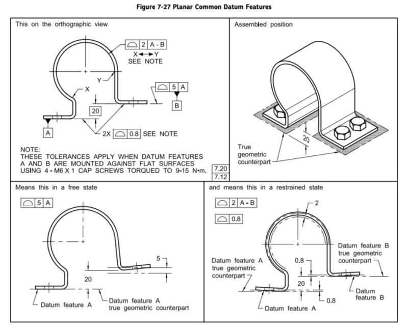
You might want to take a look at this example from the ASME Y14.5-2018 standard:

Screenshot_20240516_233229_Drive_si90cd.jpg


Check out how the 0.8 mm profile tolerance is applied in the restrained condition to datum features A and B. Additionally, the 5 mm profile tolerance qualifies datum feature B relative to A in the free state. I think this relates closely to what you were asking about.
 
Yes Burunduk, this is almost the case, thank you...one doubt: the right picture at the bottom, shouldn't be a "constrained" state instead of "restrained" state?
 
Thedesigner,

"Restrained" is the commonly accepted and standardized term to describe the condition in which the part is fastened or clamped against a fixture with considerable force.

"Constrained" on the other hand, most often refers to free state inspection - we say that the degrees of freedom of the part are being "constrained" by the datum simulation process, even when the inspection is considered to be "free state" and no considerable forces are used.
 
Think of it this way: constrained means that it's merely stopped. Restrained means that it's muscled into placed.
 
Hi, thedesigner75:

"Constrained" controls degree of freedom. It means relationships between multiple features. For example, BASIC dimension 20 in Figure 7-27 constrains distance relationship between datum feature A and B. In CMM, it means to find out best fits for datum feature A and B while maintaining a distance of 20.

Best regards,

Alex
 
Status
Not open for further replies.

Part and Inventory Search

Sponsor