Eng-Tips is the largest engineering community on the Internet

Intelligent Work Forums for Engineering Professionals

Hard Rock Hotel under construction in New Orleans collapses... 119

Status
Not open for further replies.
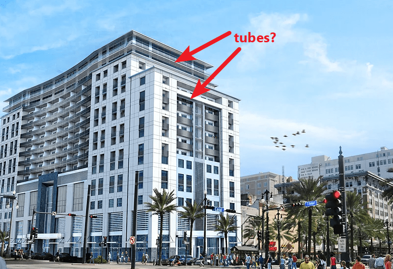
Not sure if those tubes in the picture are actually permanent structure or just shore beams to temporarily support the deck until the concrete reaches strength, perhaps the final intended end condition would match the lowest visible floor in the image posted by structuralengr89. The one flyover video post collapse appeared to show a good bit of reinf. steel in the concrete deck.

Rabbit12:
That's actually a decently large design team in my experience, similar job would be handled by a 3-4 person structural team if done by a number of the firms in my local.

Open Source Structural Applications:
 
If they were counting on the deck cantilevering over that (rather petite) beam, why would the deck change orientation? Why would such a detail be used to begin with? Maybe those tubes were to connect to part of a (structural?) curtain wall system? I wish we had a higher res picture of the tube-to-beam connections. And looking at how the tube on the column line is still oriented vertically, it seems that the tubes might not have any shear studs?

tubes_vb1w7o.png
 
@Tomfh

There's an alternate floor plan. No details seem to be shown for this floor. Tubes are shown to be final structure.

RC


Tomfh said:
Agree those tubes are probably just shoring.

I though so too, but the Permit structural drawings (S3.5A and B) show:

capture-nola2_u0wdhl.png


No backspan, and framed into a W10x19:

capturenola3_f27jrk.png
 
The deck spans in many locations (+/ 25 feet) seem quite excessive for a 3" composite deck (5.5" total slab thickness).
 
How far does this decking normally span? What sort of span to depth ratio?
 
So with that HSS outlooker detail you'd be relying on torsion in the beam and tension in the 4x4 WWF to resist the out-of-plane bending moment, correct? I sincerely hope this wasn't the intention.

However, looking at the rendering posted by dold, the cantilever on the 16th/17th level looks to be a balcony exposed to view from below. So the architect probably requested an alternative to the bent plate and gusset detail used on other levels to achieve the envisioned floating look.
 
Those spans for deck are way excessive, they can't be right but that is what those plans show.

TW
 
I guess I take back my comment on "missing something" with the HSS members in that photo... yikes!

And my Verco catalog cuts the W3/5.5" concrete tables off at a 16'-0" span, although I'm sure maybe a couple more feet (under really light superimposed loadings) could be justified by calculation.
 
I sure hope these aren't the final drawings. Every floor beam on the 16th and 17th floors is a W10x19 outside of the elevator shafts.
 
Hopefully the column sizes on the upper levels were increased beyond W6x20s.

"We shape our buildings, thereafter they shape us." -WSC
 
The final two spans (that collapsed in the video) are significantly shorter than the rest.

Maybe the failure cascaded thru the 25 foot spans as continuity was lost, and then stopped temporarily at the shorter spans.
 
Celt83, I presume the entire company can't work on this one project since I assume the firm also has other projects. The size of this project and the size of the structural engineering company seems a little disproportionate. I'm sure it's possible to complete with a small team like that but there are also other projects, marketing, etc. that must happen. I'm guessing this project really taxed that firm.
 
I think we should be mindful of where these plans just came from. The person who posted the file has only made one post since 2015, and this was it. I tried looking up that permit drawing set pdf on the NOLA website, and it did not come up in the search results. That tells me this file was posted by someone who has access to the drawings. Not sure what to make of that, but on the surface it appears to be a deliberate attempt to leak this info to the public. My apologize to carpoolturkey/johnsmith95 if I'm barking up the wrong tree here.
 
Surely that was not the final set. Its marked as a permit set and the project is listed as permit phase on the title block. But from just eyeballing it, the photos seem to reflect the member sizes on the plans. From my load tables the 3" 16ga composite deck caps out at 95 psf at an 18' span. I do not see it supporting a 70 psf load for a 26' span.

Am I reading plans right that one option for the cantilever was a huge plate and stiffeners, that doesn't seem very practical? I imagine the designer was counting on the kick backs shown in the section below to be installed with the tube option as well but there is no detail covering the tube cantilever option that i see. Either way it is a very light section to cantilever off of.
Capture_jwgjf8.png

Capture2_piublj.png
 
Ok, sorry. It just raised a red flag when your handle suddenly changed to johnsmith95.
 
The stamped permit set shows no rebar in slab (4000 psf normal wt with fiber and mesh). No way that the deck guy (or an engineer paying attention) would do that, there has to be an explanation. Maybe you could put enough rebar to make it work on paper but that would be super outside the norm.

TW
 
Status
Not open for further replies.
Back
Top