Eng-Tips is the largest engineering community on the Internet

Intelligent Work Forums for Engineering Professionals

Hard Rock Hotel under construction in New Orleans collapses... 119

Status
Not open for further replies.
The drawing index in the ARCH_FULL_SET_5.1.2019 file indicates a few more structural drawings beyond what's in the permit set. There must be a later set of structural drawings not included on the NOLA directory.
 
A couple of things bother me (sort of hinted at above):
1. Those "all around weld" symbols show the engineer doesn't know how to weld, or design welds. You don't do "all around" where the weld crosses the contact planes.
2. The kickers going up to the underside of the concrete-deck slab will induce vertical upward forces on the slab system - the WWF in the system is most likely laid directly on the deck as there is not chairing or top clear distance specified. That means the flexure in that 2 1/2" thick slab (orthogonal to the flutes) is bending essentially an unreinforced slab.


Rabbit12: Misunderstood your post if that is their entire staff agree that would taxing along with other work.

Seems the intent was for the tubes to cantilever based on the option B framing in the available permit set.

The deck spans do seem to be excessive in several areas, I keep looking in the notes to see if there is something for some kind of typical infill framing in bays.

There are also several columns with framing in one direction only, assume they are then relying on the deck to brace one axis of the column (not something I am used to seeing).
There likely is a construction or later set of drawings, don't see a single section cut on the plans in the available permit set in the steel levels.

Open Source Structural Applications:
 
bones206 - you appear to be correct, I've pulled my posts, my intent was not to spread misinformation. If others think it's usual for discussion, they can post them again.
 
carpoolturkey,
I wouldn't call it misinformation. Those were signed and sealed permit drawings posted on the NOLA website.
 
Photos from the NOLA website.


This is an area that collapsed. Deck shows reinforcing.

13_B_190114180124_1_a50ful.jpg


Reinforcing shown elsewhere too:

13B_1_190014180011_1_fn4mbf.jpg
 
After taking a good look at these drawings... What happened to peer reviews? Code review? This should have never happened.

Also the cranes appear to be Liebherr 316 EC-H. Specs on S1.4.
 
This is going to be a PRIME EXAMPLE of Why Practice ACT Structural Engineering Licensure should be Mandatory in all 50 States.

Louisiana is a Title Act State...Previously if you passed the old SE I exam, your were licensed as a PE, but Structural was listed as your field of work.

I just checked the 2 guys listed on the SER's website on the Louisiana Board of Licensure...the Owner and the 2nd PE on Staff. They are both listed as "Civil"

THIS IS WHY EVERY STATE IN THE NATION SHOULD REQUIRE ANY BUILDING 3 STORIES ARE MORE TO BE STAMPED BY A SE WHO HAS PASSED THE 16 HOUR EXAM....AN NO GRANDFATHERING!!!!


I apologize in advance because I am commenting before reading all the replies in this thread. I hope I am not repeating topics that have been settled one way or another.

(1) WIND. I was about 25 miles from the site of this collapse on Saturday morning, and I can tell you it was QUITE windy at the time of the collapse. A picnic table umbrella went airborne and almost hit someone at our Farmers' Market. Our tent was straining at its stakes, and at times we held it down by hand to make sure it didn't go airborne, too.

(2) FIRST CRASH. The man who took the best video heard clanking, took a second or two to pull over and stop his car, saw the corner sagging, and started the video. That may have taken 5-10 seconds. Did parts of the crane break first?

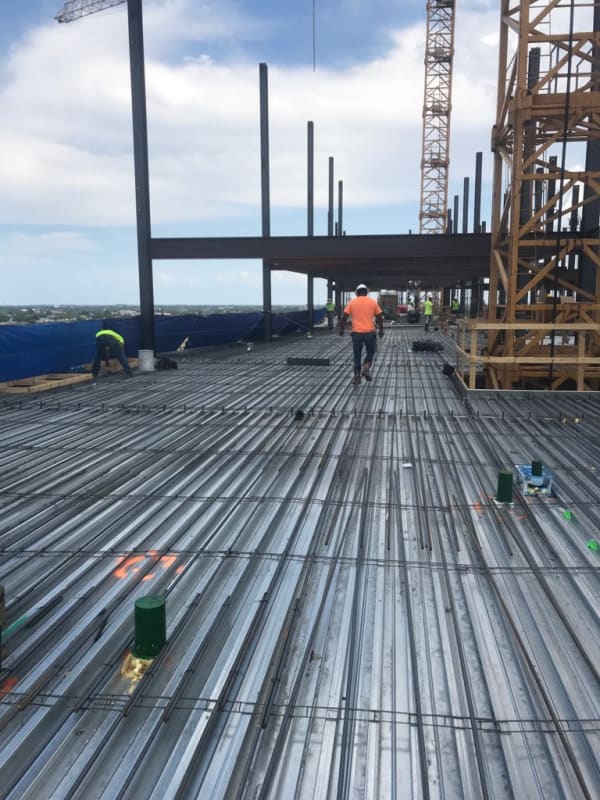
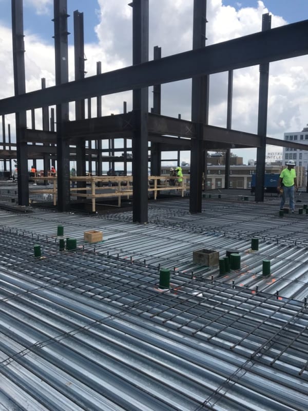
(3) SIMILAR SCHEME? Regardless of how sketchy the rectangular tubing (and associate shoring) looks, it's almost always the case that engineers repeat the basic design scheme on buildings like this, spans, direction of metal slab ribs, slab thickness, and rebar ratio. Each building is a unique design, but they wouldn't change anything radical from one building to the next, and they would have checked for reasonable agreement with previous designs. They build them in one city after another. So, the question becomes, was anything significantly different with this design?

(4) DROUGHT. Finally, this is New Orleans, and the soils are notoriously soft and still settling. We have almost been in a drought here. We had 0.17" of rain in all of September, and no rain to speak of since then. Just note that in case the wind caused some sort of problem for the support of the crane. Did the water table drop? Doesn't seem likely to have an effect, based on the mode of failure, but any unusual conditions are something to think about.

The video link posted by dold shows the man on the scaffolding without blurring (that portion has been blurred in the current version of the collapse video taken from downriver Rampart St).


@NOLA

1. My money would be on "probably not wind" in this case.

2. Not enough info to say.

3. Perhaps this engineer did not have anybody else's go-by's to copy from on this one...

4. Bigger issues upstairs.
 
(3) I rescind my comment (3) above, as I looked at the website for the structural engineer and it is a local firm that seems could not possibly have designed similar structures, as the firm has only two engineers, an EIT, and a few designers.

(1) I still think wind could have caused the crane to add stresses to the main structural system that were, perhaps, not fully planned for.

This makes my hands sweat and my heart race, like panic-mode, to see that tiny firm responsible for a complex project of this size.

 
Something I noticed from structuralengr89 post of 13 Oct 19 16:59 (showing the photo of the buckled post-shores) immediately above, the W beam connection to the column shows a bolted flange connection BUT the web plate has no bolts installed, and no field weld is visible either.


CAPTURE_NOLA-BOLTS_fdj8wv.png


I wonder if other beam/column connections had similar yet-to-be-installed bolts. The metal deck is already installed at this floor - and it unusual to delay bolt install after deck is installed.
 
The likely failure mode has to be torsion on those 25' long W10x19 girder, right?

As soon as those temporary shoring posts were removed (or started to buckle), that HSS6 cantilever + W10x19 girder system needed to take up the load from that 7' cantilever edge condition.

But how could it?


"We shape our buildings, thereafter they shape us." -WSC
 
Celt83, no worries. For all I know maybe they have some contract engineers that work for them. Their team size might have nothing to do with this failure. I just found it a tad odd.

As far as your column comment. I was taught at the beginning of my career to also have framing coming into two orthogonal sides of a column at the top. Many times I have added a small W8x10 or something just to brace the column in one direction.
 
Rabbit12, I have likewise started to wonder if this small local firm has support from a bigger out-of-state firm. Or, even a bigger in-state firm. Haeslip used to work for a bigger firm in the same building as his current office.
 
Just saying the words "W10x19 girder" inspires confidence.

What boggles my mind is how many hands this passed through and nobody said anything: Permit office, code review, STEEL FABRICATOR, steel deck supplier, GC, Architect, whoever designed the PT systems, inspectors, etc, etc, etc. AND NOT A SINGLE PERSON RAISED ANY QUESTIONS? (at least as far as we know at this point).

Deck supplier: "Hey generally we dont recommend spanning 3" composite deck TWENTY FIVE FEET, just wanted to make sure that was the intent."

Steel detailer: "Look, this isn't the first project we've worked on and some of this framing looks a little light. Is this HSS6x3 a typo? Because it is spanning 20 feet and supporting a W12 with about 200+ sq ft of trib...? And these 6x3 outriggers seem to be completely unsupported on one end, please clarify?"

If this is truly the final design for the floor and roof framing, it feels to me like somebody made a model in whatever software and no load got attributed to any of the framing. So the program just selected the lightest size to get span/depth ratio. Every single beam in thier depth class is the lightest shape (with some exceptions - W12x26, etc.). W21x44, W18x35, W16x26. But maybe not, because I can't find any rhyme or reason for some of these beam sizes.

Madness.

 
If the drawing was a preliminary - I know that in Revit, many times we populate the framing with small size beams - simply as initial placeholders.
W10x19 beams are dinky little things and I suspect that these were just in there as an initial size only - pre-analysis.
I could be wrong but that is how we roll on a lot of projects.

If these were sealed plans, then I'm off base here, of course.

Where did you get all these plans? I don't see a link above. Was the link deleted?


So what do you think will happen for failure like this? Can you use what's left? Abandon the idea and start fresh?
 
JohnRBaker said:
Some construction progress videos:

First off, let me say that this is what it looks like living in an era of drones.

Second, I can't believe that this company, Citadel Builders, have kept these Hard Rock videos up on their website. I would think that their corporate lawyers, to say nothing of their PR staff, would have immoderately ordered them taken down.
It also shows them flying the drones in violation of FAA regulations, I doubt they received a waiver.
 
Status
Not open for further replies.
Back
Top