Continue to Site

Eng-Tips is the largest engineering community on the Internet

Intelligent Work Forums for Engineering Professionals

  • Congratulations KootK on being selected by the Eng-Tips community for having the most helpful posts in the forums last week. Way to Go!

Hernando de Soto Bridge (I-40 Mephis) 19

Status
Not open for further replies.

human909

Structural
Mar 19, 2018
1,932
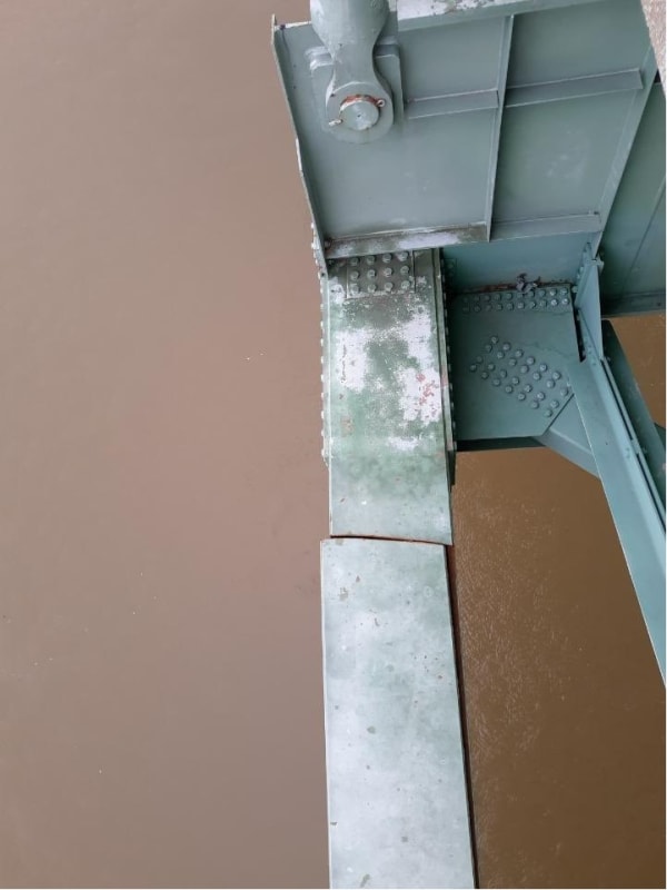
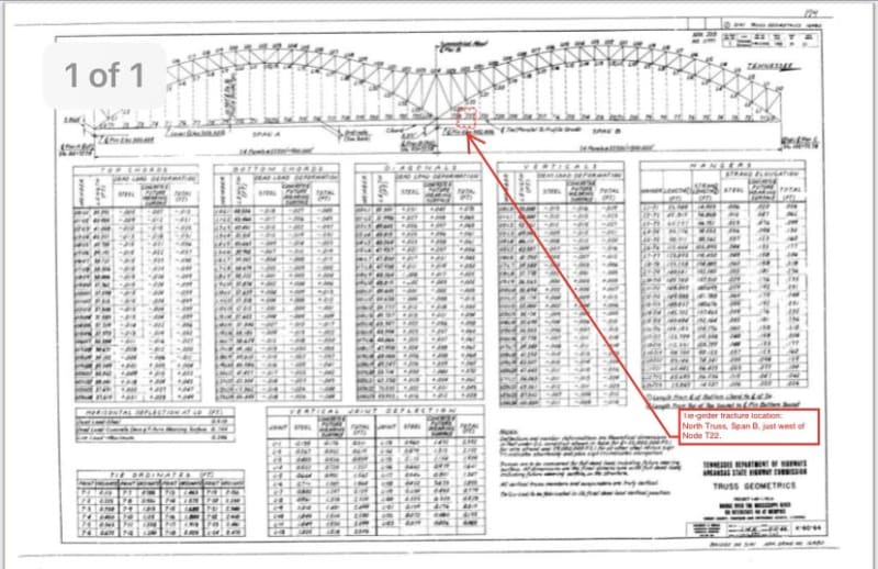
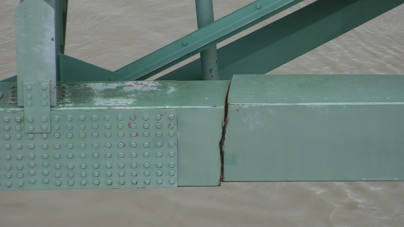
Some pretty serious looking issues here.
E1NBBdtXsAQ_Xpa_em0owc.jpg

E1NBBduWEAIJnA8_n4vt58.jpg

E1NBBduXsAAqN1p_pg4s4e.jpg
 
Replies continue below

Recommended for you

Well that is definitely "Breaking" News!
On I-40 no less.

Statements above are the result of works performed solely by my AI providers.
I take no responsibility for any damages or injuries of any kind that may result.
 
Old news.

Statements above are the result of works performed solely by my AI providers.
I take no responsibility for any damages or injuries of any kind that may result.
 
It's hard to see what's happening there with the structure. I wonder if it's passed tension into the bridge deck?
 
Also, that's a weird looking failure. It's not what I would picture for a tension failure, but it doesn't look like anything else I can think of. I can't say I've even seen a photo of a tension failure at that scale, so maybe it's just too big for the things you would expect to see. Or maybe it was brittle. It's also kind of surprising that it didn't happen at the connection zone chocked full of holes half a member depth away.

Is that what a progressive fatigue fracture looks like on a tension member?
 
Tied arch bridge. When the tie fractured, it didn't go far, so the bridge compensated by taking the load on that side in truss action. I am not a bridge engineer, but to me, that looks like the desirable redundant type design often talked about.
 
Yes, that does not look like a typical tension failure of a ductile material. Could it possibly be the result of very low temperatures during the winter?

Statements above are the result of works performed solely by my AI providers.
I take no responsibility for any damages or injuries of any kind that may result.
 
I think it may have to do with the earthquake damage mitigation changes that put high alternating loads into those members via friction pads rather than the typical rocker arrangements. That was 20 years ago, so 5000-7000 fully reversing cycles found a weak spot. It was last inspected about 2 years ago, so that's up to 700 cycles; if the fracture started on the inside at a weld defect it could have gone this distance since then.

There are other longitudinal members than the one that fractured. The structure along the sides seems to be intended to distribute any uneven loads to multiple cables and to stiffen the overall bridge deck to prevent unwanted deformations. The bottom chord is not the only one resisting the thrust load from the arch.
 
3DDave,

Do you have some drawings of the bridge? By the limited photos we have seen, I fail to understand what other tie members you mean.
 
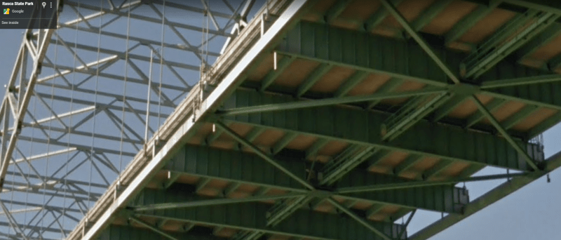
EDIT: Scratch my comments below. I, like others was assuming the deck was a truss it isn't. You can see quite clearly from google street view:

It seems that the 'beam' in question is a strut in the lateral restraint system.

I40_ewtdny.png


TLHC said:
Also, that's a weird looking failure. It's not what I would picture for a tension failure
I don't think that area is tension I believe it would be compression from hogging about the supporting tie.

hokie66 said:
Tied arch bridge. When the tie fractured, it didn't go far, so the bridge compensated by taking the load on that side in truss action. I am not a bridge engineer, but to me, that looks like the desirable redundant type design often talked about.
Did the tie fracture? I didn't hear or see about this detail.

From what I can see the truss failed at a spot that is likely under compression due to the hogging close to the tie support. Load was likely redistributed to other sections of the truss and more tension on the deck.

Cause of failure likely corrosion/fatigue but certainly outside my area of expertise.
 
Brittle fracture? no signs of triaxiality, stress risers, or weld? Dunno why it 'broke'.

Rather than think climate change and the corona virus as science, think of it as the wrath of God. Feel any better?

-Dik
 
Kinda looks like shear rupture. Especially noting that is about one section depth away from the end of the portion reinforced with plates.
 
and more...
"The US Coast Guard also put a waterway restriction in place on the river below, and there were at least 44 vessels with more than 700 barges waiting to travel the river in either direction Thursday morning, according to Lt. Mark Pipkin of Coast Guard Sector Lower Mississippi River."

Rather than think climate change and the corona virus as science, think of it as the wrath of God. Feel any better?

-Dik
 
The purpose of the tie is to keep the arch from kicking out. The broken tie could be affecting the stability of the foundations.
 
That would be my main concern, bridgebuster. They should make at least a temporary repair quick smart. Just because it hasn't moved much yet doesn't ensure it won't.
 
I guess they would need to 'jack' it back in place so that sides of the box beam line-up, and then weld some scab plates all around. Granted, it would only be a temporary repair, but it should be good enough to get by until they decide how they're going to proceed overall.

John R. Baker, P.E. (ret)
EX-'Product Evangelist'
Irvine, CA
Siemens PLM:
UG/NX Museum:

The secret of life is not finding someone to live with
It's finding someone you can't live without
 
If that is the arch tie that was severed, I think you need to find out where that force went before you can propose a 'fix'. Is that tension force now going through the deck? Or lateral bracing system? Can the foundations handle any new longitudinal forces/deflections from the sudden thrust? So much we don't know and we're all making our best guesses from some online photos. But my gut is telling me this isn't going to be a quick fix by any sense.
 
epoxybot, that picture jibes better with this description I read of the crack here:


Degges explained the structure and the crack like this: The box beam is made of steel panels that are a little under 2 feet wide and about 32 inches tall. Those four plates of steel are welded together, but three of the plates have separated, by a fraction of an inch. The bottom, fourth piece of the box beam has a crack that's about 20% the width of the steel, he said.

Maybe that helps people here hypothesize about the failure mechanism.
 
Status
Not open for further replies.

Part and Inventory Search

Sponsor