Continue to Site

Eng-Tips is the largest engineering community on the Internet

Intelligent Work Forums for Engineering Professionals

  • Congratulations KootK on being selected by the Eng-Tips community for having the most helpful posts in the forums last week. Way to Go!

How Many Datums are Too Many Datums?

Glass_Half_Full

Mechanical
Sep 26, 2024
6
Hi everyone,

Its great all the knowledgable people on this forum who are happy to help others. Hopefully one day I will be in a position where I can do the same.

I'm a bit stumped trying to tolerance a drawing I am working on, in my last job I thought my GD&T was passable but either the new field has thrown me or I have forgotten something significant.

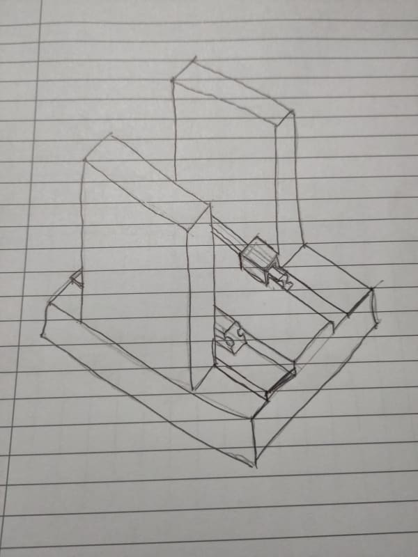
I am drawing up the base plate for a machine I am designing and it has a few major interfaces with different parts of the machine. Two key interfaces are the rails for the y-axis and the side plates that form the structure of the z-axis. I do not come from a machine tool background, and the machine I am designing represents a significant step up in precision for my company, so I don't know the established way of doing this in machine tool design.

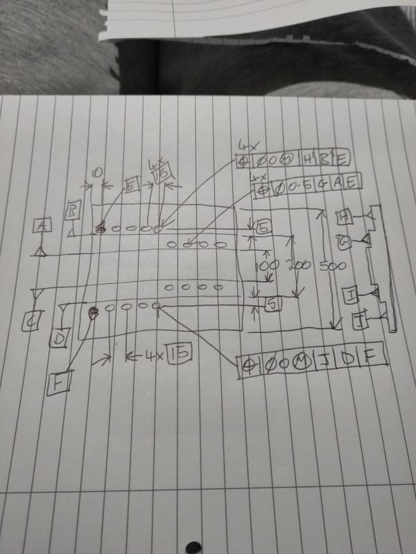
I have attached a sketch of a comparable setup of base plate with side plates and linear guide rails and an illustrative orthographic hand drawing showing the approach I am taking at the moment. Apologies but I cannot upload the actual drawing or images of the actual CAD, so I hope these are clear enough. A key detail that might not be obvious from my sketching is that the rearmost side-plate hole on either side is a dowel hole that is used as the tertiary datum for the lengthwise position of holes on that side.

But to summarise, it seems to make sense to me, functionally, that the mounting holes for a side plate should be positioned relative to the locating edge for that side plate, and the mounting holes for a rail should be positioned relative to the locating edge for that rail. This is the approach I would take with +/- dimensioning where I would dimension from each locating edge. Further, since the locating edges divide the top surface into four, I feel it makes sense for the holes to be positioned perpendicularly to the surface they sit on, and that should be the primary datum for that hole.

The upshot is that I have 11 datums on my actual real drawing, and this just seem nuts. I have probably but 5 datums on the occasional drawing before, where say it was mostly cube shaped but had a significant bore for instance. But eleven seems excessive. However it feels wrong to me to use the locating edges in pairs to create a mid-plane datum and position the holes relative to that, as then if the distance between locating edge increases (i.e. the size of the datum feature increases) the tolerance zone of the holes will not move to accommodate that and the holes will be closer to the locating edge (and misaligned with the part they interface with) than intended, and I will have to tighten the tolerance to account for this possibility.

At the same time, I really don't want to quadruple the workload of the inspector if this is going to make them do more, time consuming set ups. I have to admit my knowledge of inspection processes is lacking. If they can easily move measuring tools to check different datum reference frames then that wouldn't be so bad, if they have to move the plate into a different position in the fixturing that would be awful.

Really appreciate any insight any of you could shed on this.

Thanks.
IMG_20240926_200221_firnxf.jpg

IMG_20240926_200230_bma0gx.jpg
 
Replies continue below

Recommended for you

Seems reasonable. The inspector will have to determine where all the datum features are, so they already have the geometric basis for checking all the other features that reference them.
 
Relying on simultaneous requirements for much of that could simplify the number of datums.

 
If it was mating holes to another part simultaneous requirements might be desirable.

This baseplate is being used as a self-fixturing assembly of independent parts against the multiple datum features.

What might make sense is for the datum features to have simultaneous requirements among that group.

 
One of the things I remember from my GD&T training was to think of the datums as setup planes for inspection. I realize that with CMM that is not so much a requirement anymore, but can you achieve the proper location and sizing requirements using the same datums for multiple holes?

"Wildfires are dangerous, hard to control, and economically catastrophic."

Ben Loosli
 
Hi, Glass_Half_Full:

Design intents are not clear according to your sketch. What are those 16 holes? Are they threaded holes or holes for dowel pins? Most of those holes are for fastening purpose. You don't need tolerance of "zero at MMC" for threaded holes.

Precision rails are normally positioned by its bottom and guide faces rather than holes.

Best regards,

Alex
 
If you wanted to simplify the datum structure some things you could do is:

[li]Change the side plate mounting surfaces which are currently H & J to A1 & A2. In your drawing when you dimension the height of these mounting surfaces, use 2X along with the <CF> symbol to indicate that it's a Continuous Feature.[/li]

[li]Change the rail mounting surfaces which are currently G & I to B1 & B2. When you dimension the height of these steps you'd also use 2X and <CF> (Continous Feature).[/li]

[li]Change the first side plate locating edge from B to C.[/li]

[li]Keep the second side plate locating edge as Datum D.[/li]

[li]Change the first rail locating edge which is currently A to E.[/li]

[li]Change the second rail locating edge which is currently D to F.[/li]

[li]Instead of using the first side plate holes E & F as datums I'd use the left-most edge as a datum for locating the holes and call it Datum G because it's easier to reference an edge as a datum than a hole, especially a tapped hole.[/li]

In this scenario, for your first set of side plate holes your feature control frame would look like:

| ⊕ | Ø 0.X | A | C | G |​

The second set of side plate holes would be:

| ⊕ | Ø 0.X | A | D | G |​

The first set of rail mounting holes would be:

| ⊕ | Ø 0.X | B | E | G |​

The second set of rail mounting holes would be:

| ⊕ | Ø 0.X | B | F | G |​

You might also want to use composite positional tolerancing to loosen up the first hole positions while maintaining the required hole-to-hole requirement. Or, if necessary, multiple single segment positional tolerancing if you want to have tighter control over how far from the machined step edges those holes have to be.


Composite tolerance is a way to force the mating part out of alignment and/or position with the specified datum features. The upper segment is a tolerance of how much one does not care about location and/or alignment and the lower segment shows only the the amount of care that might matter, without correcting the problems left by the upper segment.

To see how this can happen, exaggerate the tolerances to a position tolerance of 1.0000 inch in the upper segment and 0.0001 in the lower segment.

The other suggestions could be applicable to some other application, but since no mating feature bridges multiple faces, there is no use in specifying multiple faces as a datum feature.
 
Per para. 7.15 of Y14.5-2018, the selection (hence also the number) of datum features should be based on the functional requirements of the design. Additionally, in para. 7.14 the standard says that more than one datum reference frame may be necessary for certain parts again depending on functional requirements.

Here, the funny thing is that per what is shown in the sketch even more datum features may be needed (which I like to call "global datum features"). I realize this is a simplified representation, but currently none of the patterns is located relative to the plate "main body" in X and Y directions (I am intentionally ignoring the untoleranced 10 dimension from the left side to the holes E and F, as this is not a standard way of controlling position of features). Datum surfaces A through D are also missing location controls in Y diection and datum surfaces G through J have no location controls in Z direction. This all is what the global datum features would be for.

It's generally hard to give good advice based on a simplified description like this, but if holes E and F are dowel pin holes, then it may be reasonable to consider making each of them secondary in the position callout for the other 4 neighbouring holes.
 
Using diamond pins at E and F would make sense as the long flat faces allow the vertical plates a firm location and orientation and so only need location by the pins in one direction.
 
True if the dowel pins are designed to constrain X translation only.

Edit: I wonder what mechanism ensures that the side plates remain in firm contact with the locating edges in the base plate.
 
Thanks for all the input everyone, especially 3DDave. Good to know I wasn't totally barking up the wrong tree with my approach. I had just never seen a drawing with so many datums before. I guess most examples in standards and training are kept minimalist.

To try to clarify design intent, The holes E and F are dowel holes that will have a pin pushed into them, however this pin will then be used to register the rear surface (or I guess left surface in the orientation I have drawn the base plate) if the side plates. This is why I put it as the tertiary datum. The holes adjacent to each dowel pin hole are clearance holes, actually counterbored from the bottom of the plate, which is why they are 0@MMC. The narrower holes on surfaces G and I are tapped holes for the rail fasteners, hence they have a 0.5 position tolerance.

To be honest I am realising that I have probably overly focussed on the holes when really they aren't that important (except E and F).

In my real drawing G through J are controlled using flatness and having parallelism to each other. And yes, sorry, I did leave the z dimensions off my sketch.

pmarc, I have been thinking about using profile to control the location of the main body relative to the existing datums, although my initial thoughts on how to do this involve composite datums such as B-D and E-F for example (sorry I think composite is the correct terminology, I am typing this on my phone so can't check). I'm not sure if this is a great solution.

Having said this I am surprised you said the untoleranced 10 dimension is not a standard way of controlling the position of features. Why is that? Can I not use traditional +/- tolerancing to locate datum features? I was doing the same thing to locate A through D using implied symmetry, admittedly I do need to add an explicit symmetry or location tolerance between A,C and B,D somehow as it is important. And I know GD&T replacing all of the +/- location dimensions with GD&T controls would be better, but I didn't realise using +/- dimensions was not allowed!

Sorry I realise I didn't say in my initial post, but this is an ISO drawing not ASME.
 
Glass_Half_Full said:
pmarc, I have been thinking about using profile to control the location of the main body relative to the existing datums, although my initial thoughts on how to do this involve composite datums such as B-D and E-F for example (sorry I think composite is the correct terminology, I am typing this on my phone so can't check). I'm not sure if this is a great solution.

I was thinking about making the bottom surface of the plate a global primary datum feature and two other features on the plate as global secondary and tertiary datum features. These could, for example, be left side as secondary and the height as tertiary. I don't think there is a need to define common datums such as B-D or E-F.

Glass_Half_Full said:
Having said this I am surprised you said the untoleranced 10 dimension is not a standard way of controlling the position of features. Why is that? Can I not use traditional +/- tolerancing to locate datum features? I was doing the same thing to locate A through D using implied symmetry, admittedly I do need to add an explicit symmetry or location tolerance between A,C and B,D somehow as it is important. And I know GD&T replacing all of the +/- location dimensions with GD&T controls would be better, but I didn't realise using +/- dimensions was not allowed!

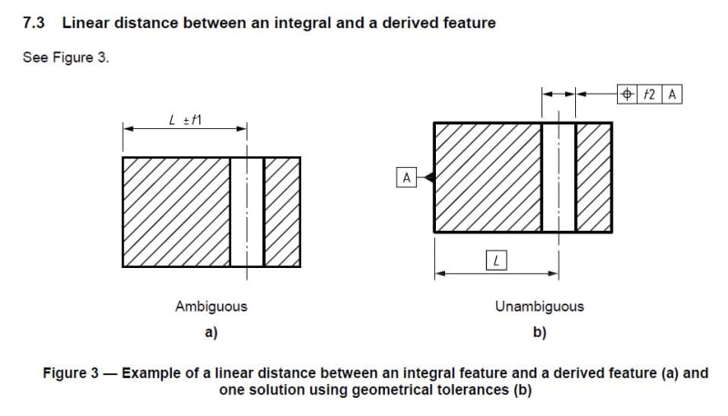
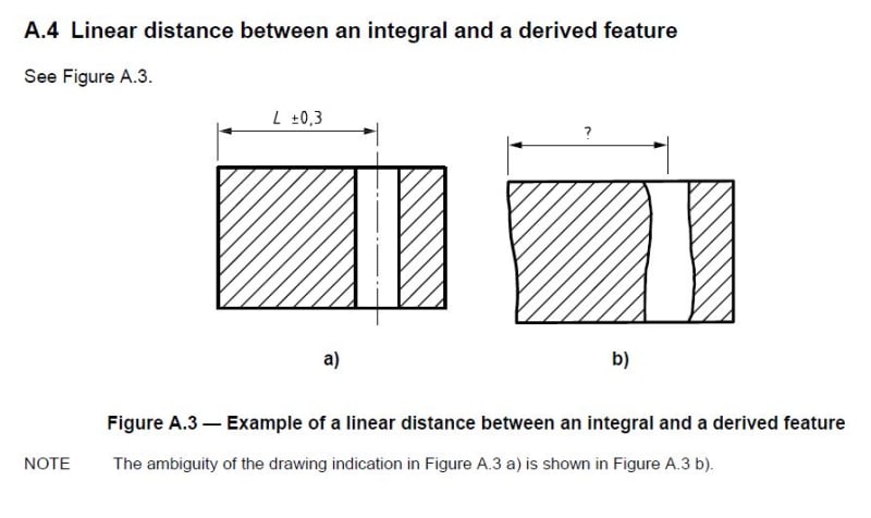
Below are two figures taken from ISO 14405-2:2011 (I don't have now access to its latest version from 2018).

a_n9vchy.jpg


b_bkx3t5.jpg


When it comes to the use of traditional +/- dimensioning for dimensions other than sizes, ISO does not say it is not allowed, but talks about them in terms of specification ambiguity that increases risk of misunderstanding the definition, hence the design intent. As shown in the second figure, there is an open question on what the +/- dimension really means. Also (this is not shown in the figure), this type of dimensioning generally does not provide clear instructions for the setup of the part for inspection, i.e., order of datums, etc. The approach I always recommend in case of requirements that are deemed non-critical/not important is to use geometric tolerances anyway (to not add to the specification ambiguity), but open up tolerances as much as possible to allow others downstream (manufacturing, inspection) to figure out what sort of trade offs may be acceptable.
 
Thanks pmarc, that makes sense, I can see how the linear dimension is ambiguous.

Is defining the bottom surface, one side, and the back surface as datums the best thing to do? Those surfaces are not particularly functional. From a function perspective wouldn't it make more sense to define the edges of the plate in relation to the established datums, which are the most functional surfaces of the part?
 
Your last question may easily turn into a philosophical dispute as there are people, I'm pretty sure, preferring different approaches.

Doesn't the base plate mate with something? The large bottom surface must probably sit flush against something, correct? What features of the plate are responsible for constraining the remaining two translation and one rotation degrees of freedom? These features I would, most likely, choose as "global" datum features and then control the "local" interfaces between the plate and other components relative to. The tolerances controlling the relationship between the global datum features and interfaces could then be generous, if truly allowed by function.
 
Following up on what pmarc said, I would add the clarification that while the datum features that were specified are functional for assembling and positioning parts on the component in question, there are certainly features intended to assemble and position the component onto the machine itself. These latter features should be used for a global datum system.
 
pmarc,
Didn't you say that the diamond pins are "unnecessarily distraction"?

I am wondering if the pins are cylindrical or diamond shaped ones?
Ref quote:
"True if the dowel pins are designed to constrain X translation only."


greenimi,

Recalling posts from 2003? On the evaluation of a datum feature reference rather than using them as an assembly component? You also mentioned the same pmarc post in Jan 2023.
 
3DDave and pmarc,

3DDave said:
Recalling posts from 2003? On the evaluation of a datum feature reference rather than using them as an assembly component? You also mentioned the same pmarc post in Jan 2023.

That's why I am asking if in ISO the rules are the same?
The OP clarified that his drawings are per ISO GPS (not ASME), hence per my knowledge (but I might be wrong here) the rules are different (at least per today's rules and not per tomorrorw ISO new revisions).
Should we use diamond pins or should be use cylindircal pins?
Otherwise stated: is CURRENT ISO GPS rules in alignment with ASME Y14.5-1994 or the current ISO rules are in agreement with ASME Y14.5-2009 or 2018?
I am leaning to say the current ISO rules are per 1994 hence a diamond pins could be used/ should be used. Or per pmarc's suggestions those diamond pins are unnecessary distractions anyway.
Hence my questions..............for clarifications only and learning the differences between the systems.
 
I have a related question if nobody minds. One way I *would* like to relate the different sides of the plate is to have the position of dowel hole datums closely tied together in the degree of freedom they control, the x-direction. However I do not want a super tight y-direction tolerance and I do not particularly need a tight tolerance from the edge of the plate to the pattern of the two dowel holes. Is there a way to achieve this using GD&T?
 

Part and Inventory Search

Sponsor