Glass_Half_Full
Mechanical
- Sep 26, 2024
- 6
Hi everyone,
Its great all the knowledgable people on this forum who are happy to help others. Hopefully one day I will be in a position where I can do the same.
I'm a bit stumped trying to tolerance a drawing I am working on, in my last job I thought my GD&T was passable but either the new field has thrown me or I have forgotten something significant.
I am drawing up the base plate for a machine I am designing and it has a few major interfaces with different parts of the machine. Two key interfaces are the rails for the y-axis and the side plates that form the structure of the z-axis. I do not come from a machine tool background, and the machine I am designing represents a significant step up in precision for my company, so I don't know the established way of doing this in machine tool design.
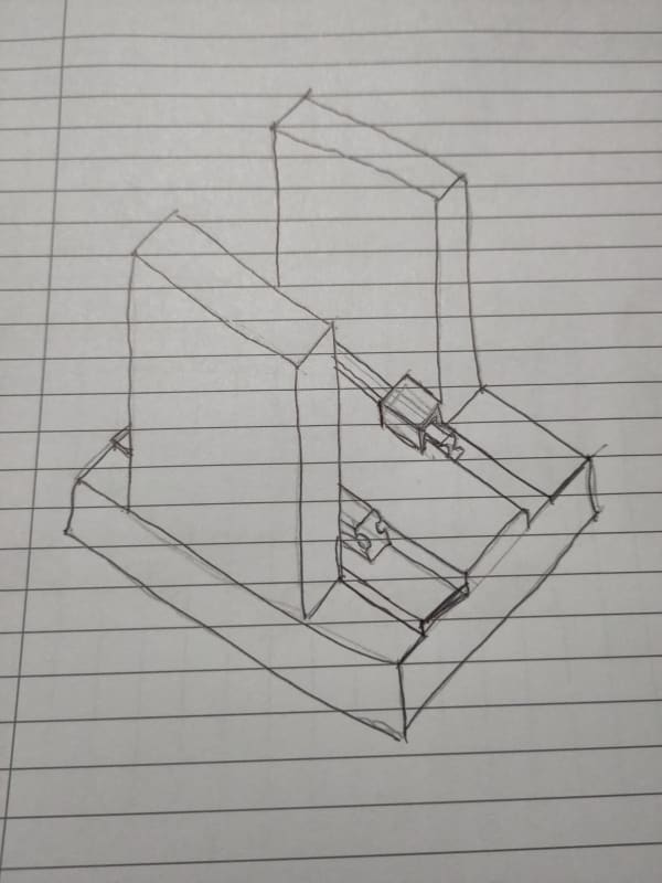
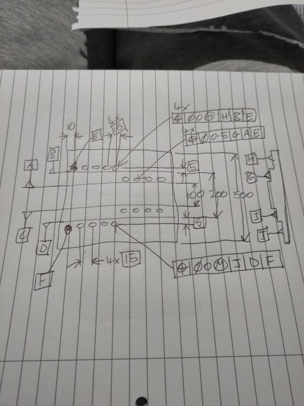
I have attached a sketch of a comparable setup of base plate with side plates and linear guide rails and an illustrative orthographic hand drawing showing the approach I am taking at the moment. Apologies but I cannot upload the actual drawing or images of the actual CAD, so I hope these are clear enough. A key detail that might not be obvious from my sketching is that the rearmost side-plate hole on either side is a dowel hole that is used as the tertiary datum for the lengthwise position of holes on that side.
But to summarise, it seems to make sense to me, functionally, that the mounting holes for a side plate should be positioned relative to the locating edge for that side plate, and the mounting holes for a rail should be positioned relative to the locating edge for that rail. This is the approach I would take with +/- dimensioning where I would dimension from each locating edge. Further, since the locating edges divide the top surface into four, I feel it makes sense for the holes to be positioned perpendicularly to the surface they sit on, and that should be the primary datum for that hole.
The upshot is that I have 11 datums on my actual real drawing, and this just seem nuts. I have probably but 5 datums on the occasional drawing before, where say it was mostly cube shaped but had a significant bore for instance. But eleven seems excessive. However it feels wrong to me to use the locating edges in pairs to create a mid-plane datum and position the holes relative to that, as then if the distance between locating edge increases (i.e. the size of the datum feature increases) the tolerance zone of the holes will not move to accommodate that and the holes will be closer to the locating edge (and misaligned with the part they interface with) than intended, and I will have to tighten the tolerance to account for this possibility.
At the same time, I really don't want to quadruple the workload of the inspector if this is going to make them do more, time consuming set ups. I have to admit my knowledge of inspection processes is lacking. If they can easily move measuring tools to check different datum reference frames then that wouldn't be so bad, if they have to move the plate into a different position in the fixturing that would be awful.
Really appreciate any insight any of you could shed on this.
Thanks.
Its great all the knowledgable people on this forum who are happy to help others. Hopefully one day I will be in a position where I can do the same.
I'm a bit stumped trying to tolerance a drawing I am working on, in my last job I thought my GD&T was passable but either the new field has thrown me or I have forgotten something significant.
I am drawing up the base plate for a machine I am designing and it has a few major interfaces with different parts of the machine. Two key interfaces are the rails for the y-axis and the side plates that form the structure of the z-axis. I do not come from a machine tool background, and the machine I am designing represents a significant step up in precision for my company, so I don't know the established way of doing this in machine tool design.
I have attached a sketch of a comparable setup of base plate with side plates and linear guide rails and an illustrative orthographic hand drawing showing the approach I am taking at the moment. Apologies but I cannot upload the actual drawing or images of the actual CAD, so I hope these are clear enough. A key detail that might not be obvious from my sketching is that the rearmost side-plate hole on either side is a dowel hole that is used as the tertiary datum for the lengthwise position of holes on that side.
But to summarise, it seems to make sense to me, functionally, that the mounting holes for a side plate should be positioned relative to the locating edge for that side plate, and the mounting holes for a rail should be positioned relative to the locating edge for that rail. This is the approach I would take with +/- dimensioning where I would dimension from each locating edge. Further, since the locating edges divide the top surface into four, I feel it makes sense for the holes to be positioned perpendicularly to the surface they sit on, and that should be the primary datum for that hole.
The upshot is that I have 11 datums on my actual real drawing, and this just seem nuts. I have probably but 5 datums on the occasional drawing before, where say it was mostly cube shaped but had a significant bore for instance. But eleven seems excessive. However it feels wrong to me to use the locating edges in pairs to create a mid-plane datum and position the holes relative to that, as then if the distance between locating edge increases (i.e. the size of the datum feature increases) the tolerance zone of the holes will not move to accommodate that and the holes will be closer to the locating edge (and misaligned with the part they interface with) than intended, and I will have to tighten the tolerance to account for this possibility.
At the same time, I really don't want to quadruple the workload of the inspector if this is going to make them do more, time consuming set ups. I have to admit my knowledge of inspection processes is lacking. If they can easily move measuring tools to check different datum reference frames then that wouldn't be so bad, if they have to move the plate into a different position in the fixturing that would be awful.
Really appreciate any insight any of you could shed on this.
Thanks.
![[bigsmile]](/data/assets/smilies/bigsmile.gif "[bigsmile] [bigsmile]")
![[banghead]](/data/assets/smilies/banghead.gif "[banghead] [banghead]")