Continue to Site

Eng-Tips is the largest engineering community on the Internet

Intelligent Work Forums for Engineering Professionals

  • Congratulations SSS148 on being selected by the Eng-Tips community for having the most helpful posts in the forums last week. Way to Go!

ISO 5459 co-axial datums 1

Status
Not open for further replies.

cr7

Automotive
Dec 21, 2019
65
Hi,

my second first post here. The first first was on ISO Standards & Certifications, but who reads that. Anyway:
I'm reading thread -> Link and looking at snip -> Link from one post.

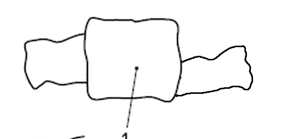
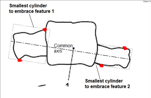
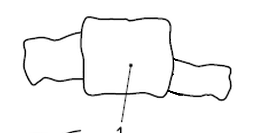
What I can't get my head around is note marked with number 6. How is the collection feature established? Center of gravity of each cilinder? I try to exaggerate the example shown even more and wonder how the datum would look like if the right cilinder was even more eccentric.
Capture_uh8qz2_xvay6c.png
 
Replies continue below

Recommended for you

Somehow like this:
Draw1_lrzvfg.jpg


"For every expert there is an equal and opposite expert"
Arthur C. Clarke Profiles of the future
 
my second first post here. The first first was on ISO Standards & Certifications, but who reads that.

This is definitely the better place to ask. It would probably be best to report your post in forum182 and request that it be deleted.


What I can't get my head around is note marked with number 6.

It refers to the constraint that the two associated features (numbers 7 and 8) must be coaxial.


How is the collection feature established? Center of gravity of each cilinder? I try to exaggerate the example shown even more and wonder how the datum would look like if the right cilinder was even more eccentric.

It sounds like your question relates to numbers 7 and 8 at least as much as to number 6. As you probably saw in thread1103-462258, I had questions on that subject as well.

Did you look at the file posted by pmarc on 12 Jan 20 14:32? I found it somewhat helpful, but it didn't completely clear everything up for me.


pylfrm
 
pylfrm, thank you.

pylfrm said:
It sounds like your question relates to numbers 7 and 8 at least as much as to number 6. As you probably saw in thread1103-462258: Datum Reference Frame for Position Control on Axisymmetric Part, I had questions on that subject as well.

Did you look at the file posted by pmarc on 12 Jan 20 14:32? I found it somewhat helpful, but it didn't completely clear everything up for me.
I see. I'm also actually reading ISO 5459.
 
I think I get it now:
cont_zzyd6q.png

So in 2D projection, there will always be 4 contact points. Which in real world (3D) would be 3 contact points on each side. I try to imagine an ideal cylinder on each side shrinking.
 
So in 2D projection, there will always be 4 contact points. Which in real world (3D) would be 3 contact points on each side. I try to imagine an ideal cylinder on each side shrinking.

I don't think that's really correct. The goal is to minimize the maximum separation, not to somehow minimize the sizes of the cylinders.

In the image where you've drawn red dots for the contact points, the maximum separation currently appears to be at the top left on feature 1. This is not optimal though. The maximum separation could be further reduced by decreasing the diameter of cylinder 1 and increasing the diameter of cylinder 2. Cylinder 2 would still make contact in roughly the same location along the bottom, but it would no longer make contact along the top. The new smaller maximum separation would occur in two locations: top center on feature 2, and somewhere (I'd guess top left, but it would be close) on feature 1.


pylfrm
 
Status
Not open for further replies.

Part and Inventory Search

Sponsor