Burunduk
Mechanical
- May 2, 2019
- 2,513
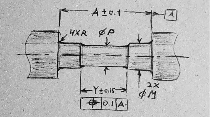
What is your way of specifying and controlling the location of a shallow spotface for which the depth is specified and is smaller than the fillet radius?
The standard is Y14.5-2009.
Thank you
The standard is Y14.5-2009.
Thank you
![[glasses]](/data/assets/smilies/glasses.gif "[glasses] [glasses]") . Thankfully, that public review draft of Y14.8 that you might have read includes a restriction that the Full Feature modifier may only be applied for tolerances specified at RFS.
. Thankfully, that public review draft of Y14.8 that you might have read includes a restriction that the Full Feature modifier may only be applied for tolerances specified at RFS.