Continue to Site

Eng-Tips is the largest engineering community on the Internet

Intelligent Work Forums for Engineering Professionals

  • Congratulations KootK on being selected by the Eng-Tips community for having the most helpful posts in the forums last week. Way to Go!

Locating a spotface 3

Status
Not open for further replies.

Burunduk

Mechanical
May 2, 2019
2,339
What is your way of specifying and controlling the location of a shallow spotface for which the depth is specified and is smaller than the fillet radius?

The standard is Y14.5-2009.

Thank you
 
Replies continue below

Recommended for you

Dean said:
The part designer is in the best position to decide when the mating envelope should be oriented normal to the surface the feature is cut into instead of the normal orientation constraint from the feature itself.

The designer can decide, but he should also be able to communicate it to manufacturing/QA in a concise way. Unfortunately, most designers will not think very deeply into it, they will use the position symbol because they are used to throw it in whenever some directly toleranced diameter or width needs to be centered or located to a datum. I wouldn't count on a clarifying note to be specified to override the default meaning of the requirement. Then it's up to the manufacturing/QA to figure out how to interpret that based on the standard referenced in the title block. In the case of a spotface there are actually at least three possible orientations of the derived axis; one may ask should the not-so-unrelated AME be perpendicular to the surface that surrounds the spotface? Perpendicular to the flat surface of the spotface itself? Parallel to the hole axis? There may be pros and cons of each option.
 
Dean Watts,

What is wrong with a feature of size being 0.05mm long?

--
JHG
 
Hi drawoh,

Any relatively short (axial length) feature of size may not be able to constrain the orientation of an unrelated actual mating envelope (UAME) in a reliable/repeatable manner. A position tolerance on a cylindrical hole, for instance, is supposed to apply to the feature axis which is the axis of the UAME. As for every sheet metal part or other thin walled part the features are so short that practical measurement means some feature other than the feature itself will need to orient the AME. I think this is OK, and sensible, but Y14.5 does not acknowledge this situation.

So I think there is nothing really wrong with a feature of size that is 0.05mm long, or any other relatively short length, but Y14.5 should acknowledge that another feature needs to be used to orient the AME is some cases. We should have a specification method so this override of the default can be explicitly specified.

Dean
 
Dean,

Speaking about UAME and its definition, I would like to ask you if there is any support from Y14.5 point of view to drive an axis from a conical surface?
In other words, if a hole 10mm ±0.5 is made as 9.5mm at one end and 10.5mm on the other how reliable an axis could be driven from this "as made" hole?
I think it is not stable and UAME could not be repeated in a consistent way.

What do you think from the theory point of view and the current offered/ shown verbiage of Y14.5?
 
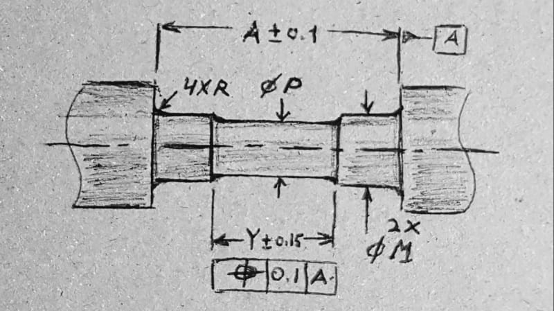
Dean and others, here's a related question about locating features of shallow depth. There is a shallow recess of diameter P and length Y turned on an M diameter shaft. All fillets are of radius R. At the ends of the recess those R radii are not fully formed because the radial depth of the recess is smaller than R. The recess needs to be located symmetrically about the distance between the faces A which is used as datum feature A. Is it a good practice to apply position tolerance as shown?

20210113_224744_ao0by4.jpg
 
Dean Watts,

If I need to constrain orientation, a long feature of size will solve the problem. If my feature of size is 0.05mm[ ]long, something else will have to control orientation, perhaps the face of the thin sheet metal. The feature can still control X/Y[ ]location.

--
JHG
 
drawoh,

Yes, that is exactly what I've state above. I'm also saying that this needs to be covered better in Y14.5. A circular element is included in the definition (list of examples rather than a definition, but in the definitions section anyway), but this question about the proper orientation for measurement is what needs to be addressed.

Burunduk,

As long as the two parallel planar surfaces (datum feature A) has sufficient capability to act as a primary datum feature, then what you have shown seems OK to me. I think the feature with width Y is a feature of size. I would have to say that is is comprised of two parallel line elements which happen be be circular line elements. What do you think of the circular line elements being considered to be parallel line elements?

Kedu,

Y14.5 should be improved with regard to supporting the axis of a cone. I find paragraph 7.3(e) Figure 7-3(e) in Y14.5-2018 that make it clear that an axis of a conical feature exists, since it is part of the datum when a conical datum feature is specified as a primary datum feature. It is only sensible then to assert that a conical feature can have a position tolerance applied which would apply to the conical feature's axis. In Y14.5-2018 mandatory appendix I, paragraph I-4 (page 307) speaks of applying a size tolerance to a gage diameter, which doesn't help us with this question. I still wouldn't hesitate to apply position on a conical feature. If you happened to read the public review draft of the next version of Y14.8 "Castings, Forgings, and Molded Parts" you may have noticed the "Full Feature" <FF> modifier, which clarifies that a position or perpendicularity tolerance applies to the axis of the full feature if a size (with +DFT, -DFT,or "Draft adds material" or "Draft reduces material) and associated feature control frame are applied to a drafted feature (a cone or wedge). The tolerance zone for these Full Feature cases will be a cylinder for a conical feature (drafted pin or hole) or two-parallel-planes (drafted slot or wall).

Dean
 
Dean,

Dean said:
Y14.5 should be improved with regard to supporting the axis of a cone. I find paragraph 7.3(e) Figure 7-3(e) in Y14.5-2018 that make it clear that an axis of a conical feature exists, since it is part of the datum when a conical datum feature is specified as a primary datum feature. It is only sensible then to assert that a conical feature can have a position tolerance applied which would apply to the conical feature's axis. In Y14.5-2018 mandatory appendix I, paragraph I-4 (page 307) speaks of applying a size tolerance to a gage diameter, which doesn't help us with this question. I still wouldn't hesitate to apply position on a conical feature. If you happened to read the public review draft of the next version of Y14.8 "Castings, Forgings, and Molded Parts" you may have noticed the "Full Feature" <FF> modifier, which clarifies that a position or perpendicularity tolerance applies to the axis of the full feature if a size (with +DFT, -DFT,or "Draft adds material" or "Draft reduces material) and associated feature control frame are applied to a drafted feature (a cone or wedge). The tolerance zone for these Full Feature cases will be a cylinder for a conical feature (drafted pin or hole) or two-parallel-planes (drafted slot or wall).

Thank you very much for your input. I appreciate your insights.
May I ask a follow up question: How would you calculate the virtual condition boundary for such features? Are you going to use MMC from the size or MMC + (plus) or - (minus) the draft?

In other words is the axis interpretation still usable or maybe the surface interpretation is the only one interpretation required?
(again, I am assuming your acceptable position applied to a cone is modifed at MMC or LMC).
I think the virtual condition boundary (VC) is a cylinder and not a cone, didn't it?
What do you think?


I really appreciate your input in this matter.
THANK YOU!!

 
Lets say a drafted holes shown with -DFT 10± 0.5 , position Ø0.15(M) |A|B|
with a draft of 1° angle.

What is the VC (calculated value) of this hole?

VC= 9.5 minus 0.15
or
VC = 9.5 minus 0.15 minus some additional value coming from 1° angle at the maximum depth of the hole


Thanks again

 
Hi Kedu,

Uh oh, yet another very good question [glasses]. Thankfully, that public review draft of Y14.8 that you might have read includes a restriction that the Full Feature modifier may only be applied for tolerances specified at RFS.

The entire surface method vs. resolved geometry (axis, etc) method issue is another thing that needs to be improved, or in this case eliminated from Y14.5 in my opinion. For now, I would recommend that either profile of a surface or position (without the <FF> modifier) be used if (M) or (L) is the functional case for drafted features. This means that the evaluation can only sensibly be the resolved geometry method, since the +DFT or -DFT size tolerance only applies to the mold line (either a circular mold line or two parallel line mold line, depending on the type of feature). I don't think the surface method can be used for this case.

Not a perfect solution, but it's what we have for now.

Dean
 
Dean,
Thank you for your informative responses. It is great to learn about the FF modifier from the Y14.8 new draft and position application to non-parallel or non-cylindrical Features Of Size (?).
By the way, is there access to this draft anywhere online?

Regarding the recess edges example - I'm fine with circular line elements being considered to be parallel line elements. My concern was that the feature may not be considered a FOS or a good feature to apply position to, since it may not physically constrain an unrelated actual mating envelope that normally attempts to expand/contract until stopped by the feature it is associated with (it is derived from the wording of the AME definition). One assertion I encountered in the past in this forum and elsewhere is that if a feature cannot constrain an unrelated actual mating envelope it is not a FOS. I think this is why parallel but non-opposed (offset) planar surfaces are not considered features of size by the majority. One may ask- If we are to accept features that are unable to stabilize the orientation of, or restrict the expansion/contraction of an Unrelated AME as features of size because we can, for example, use a vision system to determine some best fit "envelope" for the feature and derive an axis or center plane from it (as with the recess edges), then why should features lacking opposed points be excluded from the FOS category?

And a question regarding the application of position tolerance to a conical feature - how should this look like on a drawing? Would the feature control frame be associated with the base or truncation diameter? Or perhaps a better option - Some gage diameter at a basic distance from the apex or base? Am I right in my understanding that in these cases only the new FF modifier from the Y14.8 public review draft you mentioned can provide an unambiguous meaning to what the tolerance applies to (axis of the entire cone versus a specific circular element)?
 
Dean said:
For now, I would recommend that either profile of a surface or position (without the <FF> modifier) be used if (M) or (L) is the functional case for drafted features. This means that the evaluation can only sensibly be the resolved geometry method, since the +DFT or -DFT size tolerance only applies to the mold line (either a circular mold line or two parallel line mold line, depending on the type of feature). I don't think the surface method can be used for this case.

Dean,
Thank you very much.

I know you are not THE committee (and you are in the committee), but what are the reasons YOU think the surface method is not appropriate for those applications with M or L modifiers?

And I would like to ask you, since the standards do not provide the reasons of changes: why do YOU think the committee decided put a kibosh on using FF modifier for features with MMC/ LMC and they restricted to RFS only?

Thank you again for your advice


Hi Burunduk,

I think those circular elements creating a feature of size are just as valid as the line elements at the ends of an elongated hole. I also would say that anything that can be measured with a CMM can be measured with hard gaging, but in some cases some special tooling may be needed to minimize uncertainty and enable the hard gaging measurements.

I think features lacking opposed points can be interrupted features of size. Actual local size as it is currently defined, with all the various ways people are left to "interpret" it, is a problematic definition and maybe even concept. I really hope the next version of Y14.5 fixes the problems with it.

Drafted features that have 2D size tolerances applied at one end or the other (at the mold line), or with basic dimensions locating size tolerances at specific location(s) on a drafted feature, are not features of size. They have an axis or center plane, similar to a feature of size, but they do not constrain a mating envelope like a feature of size does. So, I think position should be thought of as a tolerance that can be applied to an axis, center plane, or center point rather than a tolerance that can be applied to a feature of size.

Hi Kedu,

The <FF> modifier applying only at RFS is a restriction that could be said to be because extending it to tolerances applied at MMC or LMC will be difficult, so this will be addressed in a later version of Y14.8, but I would not agree with this view. I think the <FF> modifier should always and forever be restricted to RFS only. As I said above, a drafted feature will have an axis or center plane, but it is not a feature of size. I think the existence of tolerances modified at MMC or LMC is a source of great confusion, to the point that I think they should be deleted from the language. They have lots of history behind them though. For technical reasons, I think it would be a no-brainer to come up with a better way to apply a single boundary surface control, as tolerances modified at MMC or LMC always should be thought of as doing. From a people and politics point of view though, this change will be very difficult to make.

I think it is the "axis interpretation" (resolved geometry method, to use a better term) for tolerances at MMC or LMC that needs to be deleted from the standard. For tolerances at RFS, the mating feature should center within the considered feature, so the axis, center plane, or center point is a relevant feature element that a position tolerance should be used to control. For MMC or LMC, the functional case is that clearance/space must be available for MMC, or material must be present for LMC. Since the mating feature will not center itself within the considered feature the axis is not relevant (or not relevant enough) for these cases, the surface is the feature element that should be controlled, from a functional point of view. I don't think position or straightness or flatness or an orientation tolerance at MMC or LMC is the best way to specify a surface control, but over 50 years of history with this convoluted approach will make this difficult to change. Some may argue that the results from resolved geometry method and the surface method differ very little, with the resolved geometry method just being more conservative. My reply to that is that a more conservative result will lead to rejection of parts that are functional. When the parts cost a few pennies that may not be a big deal, but in some industries each individual part can be very expensive. I think we need only one method that clearly addresses the feature surface for these cases.

If I had more time this morning I might have been able to say some of this more efficiently. I hope this explains well enough what I am trying to say.

Dean
 
Dean, that's a very interesting approach. So to summarize it, If I understand you correctly - you would like the axis/center plane interpretation of position tolerance at MMC/LMC to be eliminated, and the surface interpretation of the same tolerance to be replaced by a different new symbol and term. That way position would only be applicable at RFS and always control the axis or center plane. Do I get this right? It does make a lot of sense to me.

Would you like to achieve a condition in which we can distinctively categorize geometric characteristic symbols to those that are used to control the surface only and those that are used to control the resolved geometry only? I think it could make things less confusing for those learning GD&T, but it may require a massive reworking of the entire standard.
 
Hi Burunduk,

Yes, you have summarized my likely to be wishful thinking correctly. Over 50 years of history with the current approach makes no more tolerances modified at MMC or LMC and a separate way of specifying a single boundary that applies to a surfce a tough sell.

Dean
 
Dean, I think that realizing it would require adding at least 3 or 6 new symbols to replace current MMC/LMC controls (surface interpretation)- you would need replacements for position at MMC, position at LMC, straightness at MMC, straightness at LMC, flatness at MMC, flatness at LMC. All those completely separated from the position, straightness, and flatness sections/subsections of the standard.
Do you see it differently?
 
Dean

Dean said:
For MMC or LMC, the functional case is that clearance/space must be available for MMC, or material must be present for LMC. Since the mating feature will not center itself within the considered feature the axis is not relevant (or not relevant enough) for these cases, the surface is the feature element that should be controlled, from a functional point of view.


Let me ask you a straight forward question:

If a drafted feature with <FF> modifier is also modified at MMC/ LMC (for functional reasons) AND a note is added to clearly specify that only surface interpretation shall be applicable (in other words canceling the resolved geometry method) then what do YOU think can be the unintended consequences of such approach?

I am just curious about your arguments against my solution above. What do you have against it? (and I am not saying it is flawless, but I am not seeing it as a nonsense either)
(again, <FF> at MMC/ LMC with surface interpretation ONLY).

Thank you again for your pertinent advice.

 
Hi Burunduk,

It could be done using profile of a surface if there was a method for specifying the MMB and LMB as separate values that comprise the profile tolerance zone (I also think the use of the terms MMB and LMB should be expanded beyond datum features, so we could then eliminate the terms virtual condition, inner boundary, outer boundary, resultant condition and worst case boundary). Then we just need to add a method to turn one of those boundaries off to create a single boundary tolerance that would apply to the surface, just as the surface method for all tolerances at MMC or LMC will create.

It turns out that using profile with offsets from true profile to accomplish this is not an intuitive looking spec though. Pmarc has come up with a better way (in an email discussion). I won't speak too much for him, but with his better way, the same straightness, flatness, orientation, or position tolerance would be specified but with a method to clearly specify a single surface boundary (just like the current virtual condition boundary would have been) by indicating that the feature surface must be on a particular size of a boundary specified as the diameter of a cylindrical boundary or the width of a two-parallel plane boundary (for a "width" type of feature).

Either way a large number of additional symbols would not be needed.

Hi Kedu,

My concern about expanding use of the <FF> modifier to drafted features with tolerances modified at MMC or LMC is that it would require that those boundaries be constrained in translation in the features axial direction (for conical features) and a similar restriction for wedge features. Since the surface boundaries must be tapered to match the theoretically exact draft angle, they become variable in size if they can translate in the axial direction. This make them similar to controlling a conical feature with profile, for which an axial translation constraining datum feature is a must if more than form and coaxiality are to be controlled (to control the "size" of the cone). This consideration does not exist for cylindrical or width features, so I think this is at least an odd difference. I think a bigger issue is that we would have to extend local size to tapered/drafted features as well, since the feature being within its size limits is the other requirement that goes along with a tolerance at MMC or LMC. We have a hard enough time trying to define and work with local size for simple features of size. Extending local size to drafted features isn't something that I think we should do.

Dean
 
Dean said:
My concern about expanding use of the <FF> modifier to drafted features with tolerances modified at MMC or LMC is that it would require that those boundaries be constrained in translation in the features axial direction (for conical features) and a similar restriction for wedge features. Since the surface boundaries must be tapered to match the theoretically exact draft angle, they become variable in size if they can translate in the axial direction. This make them similar to controlling a conical feature with profile, for which an axial translation constraining datum feature is a must if more than form and coaxiality are to be controlled (to control the "size" of the cone). This consideration does not exist for cylindrical or width features, so I think this is at least an odd difference. I think a bigger issue is that we would have to extend local size to tapered/drafted features as well, since the feature being within its size limits is the other requirement that goes along with a tolerance at MMC or LMC. We have a hard enough time trying to define and work with local size for simple features of size. Extending local size to drafted features isn't something that I think we should do.

Dean,

I am thinking that the virtual condition boundary (the surface that cannot be violated) is to be calculated from the size dimension only and not from the drafted one.
So the surface boundary (VC) is a cylindrical surface and not a conical one (also a width VC boundary is a WIDTH and not a wedge)

In my previous example, lets say a drafted holes shown with -DFT 10± 0.5 , position Ø0.15(M) |A|B|
with a draft of 1° angle.
If by decree the VC is calculated as VC= 9.5 minus 0.15, THEN what do you think are the risks of such approach?

Why are you saying that the surface boundaries MUST be tapered? Why the VC callot be forced to be "straight" (cylindrical or width and NOT conical or wedge)

I am sure I am missing something.....

 
Kedu said:
I am thinking that the virtual condition boundary (the surface that cannot be violated) is to be calculated from the size dimension only and not from the drafted one. So the surface boundary (VC) is a cylindrical surface and not a conical one (also a width VC boundary is a WIDTH and not a wedge)

Kedu, my understanding of the problem is that the FF modifier indicates that the full feature is being evaluated, but a cylindrical or parallel planes VC boundary will only be related to the applicable size limit of a local cross-section. To consider all local sizes along the feature the VC boundary needs to be tapered, which introduces the axial constraint problem Dean addressed.
 
Status
Not open for further replies.

Part and Inventory Search

Sponsor