[/Those are not the correct plans for anything resembling as-built as far back as ‘81.]
Santos81, I agree Sheet 5 of the Structural Plans I posted above is from the Surfside archives and is a 1979-80 Vintage Design Drawing. I would think 'As-Built' Drawings are just mark-ups of the Design Drawings to reflect changes back in 1981, as plans were paper back then on job sites, and not digital.
I can't image a builder deleting or adding concrete columns or beams in his as built, without consulting the design engineer. However, what they have uncovered so far, says this builder/developer may have been making lots of changes without getting approval from the EOR. So who knows what as built would really look like on this project, and now most of the evidence is gone.
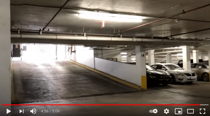
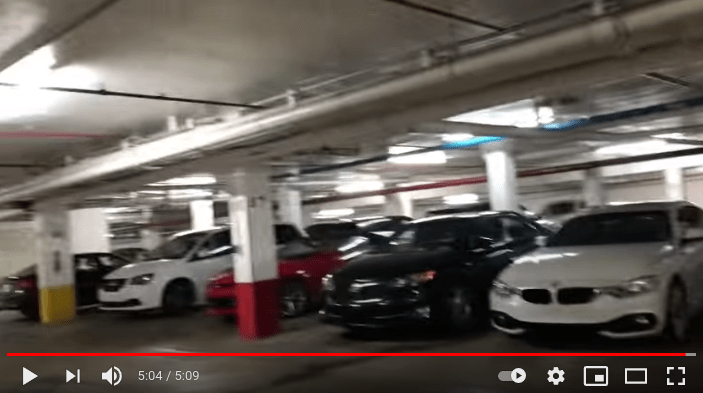
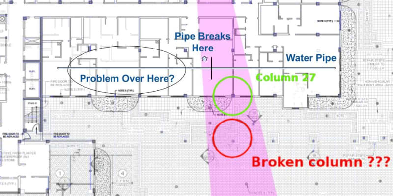
My only point was comparing design drawings to the video from 2020, you can clearly see the Beam between column 27 and 28, which is consistent with the 1979/80 design drawing I posted. Thus, in this case as built looks a lot like the design drewing.
Point of my post was the building is tied firmly to the planter deck area, so any deterioration of the planter area is not isolated structurally from the building, thus failure of deck causes progressive failure of building.
This looks like a terrible idea to not have isolation joint between building and elevated patio deck.