Eng-Tips is the largest engineering community on the Internet

Intelligent Work Forums for Engineering Professionals

Miami Beach, Champlain Towers South apartment building collapse, Part 08 20

Replies continue below

Recommended for you

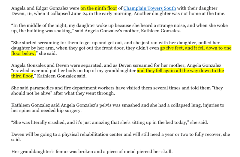
The Gonzalez family Unit 904 -


Brief facts in a nutshell version -

ScreenHunter_392_xacr16.png


They ran out the door, got 5 feet and that slab dropped one floor. The mother had enough time to crawl over and get on
top of her daughter to try and protect her. 5 seconds...10? Then they dropped from 8th to 3rd floor.

That last line about the daughter is tough.

And somehow Binx their cat survived too!
 
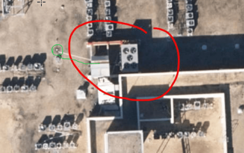
Have we any indication of where this cable in the steel support permit denial is, and if it did have a turnbuckle attached? Where would this cable have been anchored?

Edit: Ha, nope.
 
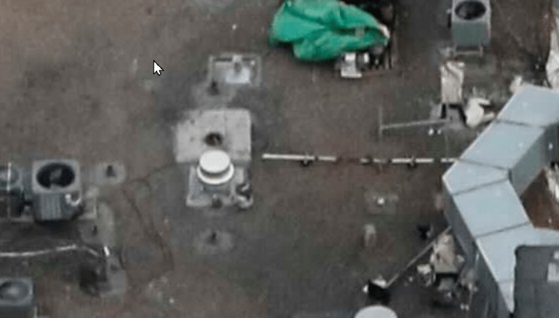
Demented, a cable attached to the AC unit? I know I saw a picture that showed a bit of it, and later a hole where I assumed it was yanked out. I'll try to find it.
 
Seems that was the plan for the denied permit. Was it just held down via tensioned cables anchored to the building? Maybe thats what the tearout on the remaining beam atop the column we see in the controlled demolition. The thing from the other side in the drove video we know had no rebar in it. Plus that field report. That would be an ooopsie. A lot of oopsies.
 
That would appear to be a PVC drain. It's more visible in the 4k drone video.

Precision guess work based on information provided by those of questionable knowledge
 
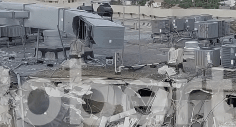
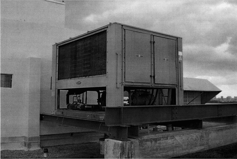
I find this photo interesting, in that there is no concrete beam at Penthouse Corridor like there is shown on original Plans, and even on revised original plans. This Penthouse Addition was changing on the fly, IMO.... Originally there were 2 concrete beams spanning columns at each end. 2019 Photo shows one end of platform hanging off West CMU Penthouse corridor wall.

Could their 'Value Engineering' have eliminated the 2nd concrete beam, by just hanging off CMU wall? Photo as-built does not match any version of original design I could find.....

Edit notice column line on left of hanging AC supports


image_k7czgs.png


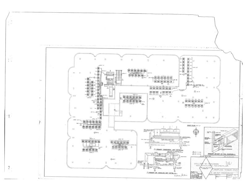
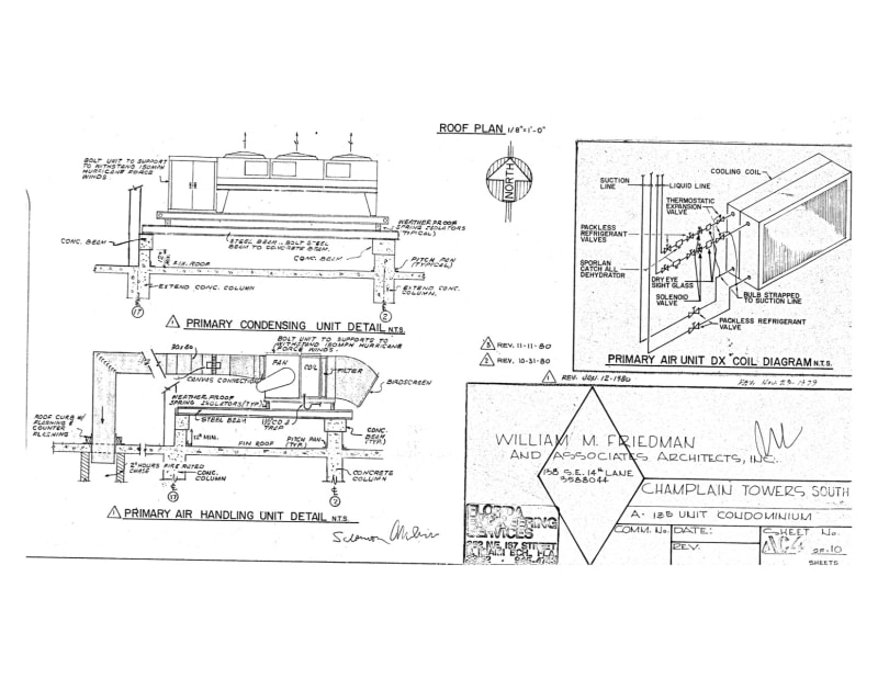
Here is one version of AC support beams, and I will look for plan that has revised 1980 date too.
AC_Beams_pnugvj.jpg
 
Demented said:
We also have the elevator in use at the time, pulling a heavy load up from the roof.

With only two people in it, the elevator should have been falling upwards, controlled by motor braking. Properly configured, the counterweight should balance the elevator car at roughly half load, so they fall upwards when lightly loaded. All of the weight for it should have been directly supported by the RC shear wall structure, and it shouldn't have been putting much dynamic load into the building as a whole.
 
@Thermopile
That was my thought exactly.
Loss of support. F=MA
This support was to stop the roof collapsing.

The steel beams look like it's held with the typical 4"x4"x.25" steel clip with 7/8" slotted holes to accept a 5/8" Hilti anchor.

@Murph9000
Thank you for explaining that.
 
#Demented, And failure on West side AC area would be hidden by East Penthouse Corridor Wall in the Security Cam video.

Edit, Slab could have failed under CMU West penthouse wall, well before columns actually failed with AC load on CMU wall and not column line
 
Notice Revision 1 and 2 from Oct 31, 1980 and Nov 11, 1980.... Very fluid changing design, and perhaps pressure to get done ASAP... Sorry this is AC4 I posted. You can find it in several of Surfside PDF's both with the revision dates above

Nov_1980_CB_Rev_czocjn.jpg
 
Why extra steel beam on top of steel beams sitting on concrete beam on one end, and hanging on CMU wall on other end?

Was extra top steel beam, a bandaid fix for failing concrete beam in 2009?
 
The permit was requested AFTER the new install. I think the unit may have been overweight for the structure. We could already see the fabricated beam had a slight arch to it, and the weight was hanging from it if that concrete beam was considered inop for what ever reason. This severely changes the load capacity of the beams with their construction.

The extra top beam was the temporary support structure to eliminate shoring of 3 floors down during the beam replacement. It was to have no load bearing capabilities. It was just to hold the unit up while the beam was replaced from end to end. The portions left on the column should have been tied into the new beam, but seems they were not properly. This could very easily lead to a shear of the concrete beam due to overloading and uneven pressure being applied by an overloaded and sagging steel beam on very suspect concrete.

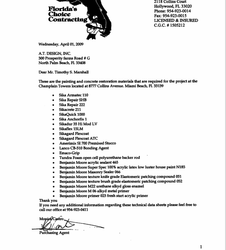
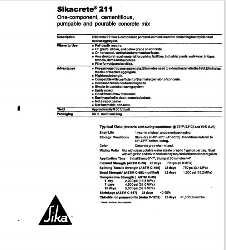
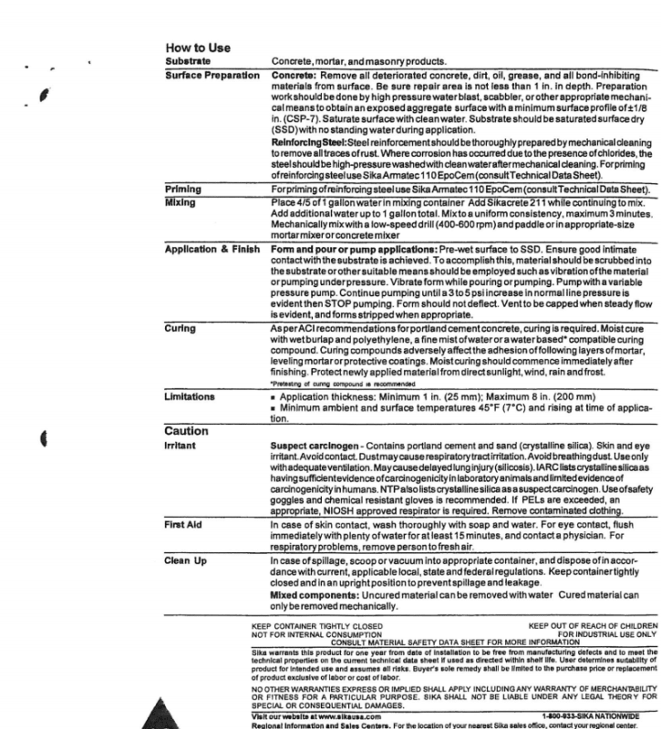
Edit: Time to go dig the spec sheet out for that concrete repair.
 
Status
Not open for further replies.
Back
Top