Continue to Site

Eng-Tips is the largest engineering community on the Internet

Intelligent Work Forums for Engineering Professionals

  • Congratulations SDETERS on being selected by the Eng-Tips community for having the most helpful posts in the forums last week. Way to Go!

Miami Beach, Champlain Towers South apartment building collapse, Part 17 14

Status
Not open for further replies.
Replies continue below

Recommended for you

thermobaric (Military) said:
Here is Structural Magazine Recommended details on offset columns. Spoiler alert, additional layer of rebar....

Not only that but the (additional) bottom bars are to be skewed to line up between offset columns. This allows for "constructability" by leaving the two standard layers orthogonal.
 

A computer design may have helped, but there were other more serious problems. Even the remedial work was not intended for a corossive environment. I've done 20 storey buildings using two cycle moment distribution... FEA is not a panacea.

Rather than think climate change and the corona virus as science, think of it as the wrath of God. Do you feel any better?

-Dik
 
SFCharlie said:
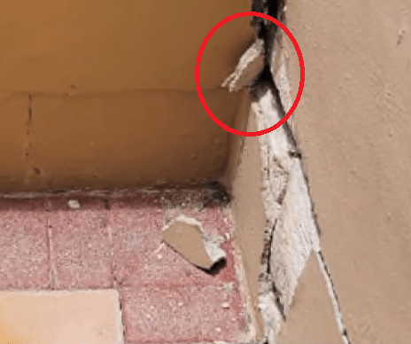
The red ovals have been IDed as elastomer, possibly from a previous repair.

@SFCharlie, you were right. I found another image that shows the lower feature, I had thought was a root or branch, from the side. It is clearly part of the stucco.

Stucco-side-view-not-root-or-branch-crop_rwf9cs.png


I still think the top of the long planter wall is tilted inwards towards the plants and that explains why the section above the horizontal crack doesn't have additional exposed cracks, because the inside edge is acting as a hinge and all the weight of the wall remains supported. There is no need to lift the weight of the wall, so if a root or branch was growing through the vertical crack it only has to tilt the top the the wall.
 
IanCA said:
I still think the top of the long planter wall is tilted inwards towards the plants

It’s hard to imagine a retaining wall tilting toward pressure as it fails. Moreover, sudden vertical vertical or horizontal retaining wall damage is very unlikely to be caused by root systems. In my experience, root system damage is slow and inexorable, causing retaining walls to bulge. If any tilting occurs, the retaining wall tends to tilt out from the top.

St. Louis has historic neighborhoods where many houses have brick or stone retaining walls by the sidewalk that are similar in height to the CTS planters. Those that are failing are most often bulging away from the plantings because the root systems apply slow pressure from behind them and push them forward toward the sidewalk until the bulge starts popping mortar. At that point the wall gets dug out and relaid. There is no vertical movement up or down.

I have also seen retaining walls with a sloping terrace above them tilt outward at the top and develop vertical cracks beside the section with the greatest tilt. This is caused by the pressure of the sloping terrace slowly moving downhill over time. In these cases, though, the tilting section does not drop vertically lower than the sections next to it, and the only part of the wall that might fracture horizontally would be at the sidewalk level.
 
IanCA said:
I still think the top of the long planter wall is tilted inwards towards the plants
MaudSTL said:
tilt outward at the top and develop vertical cracks beside the section with the greatest tilt

Could we be being seeing torque induced crack due to offset columns with no skewed rebar to resist offset column torsion loading? This would also explain the diagonal crack running form K15 to K13.1 and perhaps onto Column 76?

Parking deck and planters create a tremendous torsion loading on K line under planters, due to unbalanced moments?

Edit: I have experienced exactly the retaining wall failure MaudSTL is describing. In my case a large tree is causing the push in one direction with vertical cracks on each side. Rotating wall outward from the base of wall. So sloping wall from base to top.

In my reading, unbalanced moments at offset columns creates uneven punch shear.

Also the crack under planters inside wall running E-W along parallel to south wall, is discussed by CE&FA. Where he states there is a dynamic loading in that area due to cars turning into parking spot then applying brakes. Note crack E-W just in front of car front tires along that wall.

 
thermobaric (Military) said:
with no skewed rebar to resist offset column torsion loading

The rotation moment has been there for 40 years. I think the question is why did it stop resisting in any plane after so long? The concrete turning to powder is not predicated much on the angle of the bars. It's interesting to note perceived design flaws. But it could be a red herring. If the deck is rotating down there centered at a column and it has proper stiffness wouldn't it go up at the other side?
 
Zebraso said:
If the deck is rotating down there centered at a column and it has proper stiffness wouldn't it go up at the other side?

Yes, I think you are correct! Which leads us back to concrete degradation could have been problem, and any rebar issues were secondary?


Edit: The fact that building stood for 40 years, despite what appears to be design defects, correct and/or flawed repairs, deferred maintenance, remodeling adding weight, etc., indicates to me this failure is a systems problem and not just something that can be measured thru finite element analysis of what the potential 'as built's were.
 
Yes, likely. However the cracks may have been "accelerated" or encouraged by the moment. The the car weight helps too. Membrane ends there. Water under membrane into cracks?

Edit: meh. deck rotating down on planter column might explain the elongated crack in the planter box. Dang.
 
thermobaric (Military) said:
not just something that can be measured thru finite element analysis of what the potential 'as built's were

Yeah, you don't need FEA if you can tell the columns are already over loaded or lack margin without it. That was what the second drop beam was for right? So was an error in calculations made when the beam was removed? Cars were lighter back then?
 
One of the recent videos shows gravel from the neighbor's sidewalk coming through the south wall. The rebar (that anchored the pool slab to the wall) is broken (not zipped) at the wall. To the east, a moderate distance away, short lengths of zipped rebar are visible. Farther east, where the building was brought down by controlled demolition, the rebar zipped full length.

SF Charlie
Eng-Tips.com Forum Policies
 
SFCharlie (Computer)(OP) said:
The rebar (that anchored the pool slab to the wall) is broken (not zipped) at the wall.

The Lehman FEA simulation included missing rebar in that location as well as corroded rebar. If I may quote from MH:
"The results: Corrosion, plus the removal of some connections between the pool deck and southern perimeter wall seemed to set the stage for progressive failure across the western half of the pool deck and into the tower through a vulnerability behind the elevator shaft, in the crook of the “L-shaped” building."

Read more at:
That is the basis for the cracking and deflection graphics that have been posted here before. Now having included that info I think "seemed set the stage for" is a mouthful. According to MH it take 20 hours to run the full model on a super computer. I assume that FEA that is used in design method say in autodesk does not yield this type of data.
 
MaudSTL said:
If any tilting occurs, the retaining wall tends to tilt out from the top.
@MaudSTL Yes, I agree with all of your points, but I do see some other indications that suggest the displacement was not entirely vertical. I don't disagree that the deck was irregular and was showing signs that justified further investigation but I'm not sure the vertical displacement was as much as has been suggested.
 
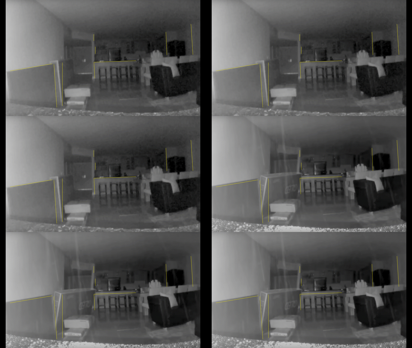
Ring Cam footage and why Column L9.1 (along with K9.1) collapsed first, in simple terms.

To start, I chose an early frame and a later frame, aligning them with the credenza as a reference. Apparently, the camera has shifted slightly on the credenza though it remains in a very similar orientation w.r.t. the front line of the surface (the shift was 7 pixels left/right and 1 pixel up/down).

Ring_Trapezoid.04_zyaqvu.gif

.
.
.
.
.
. Gratuitous spacing 'cause the two images don't sync well.
.
.
.
.
.

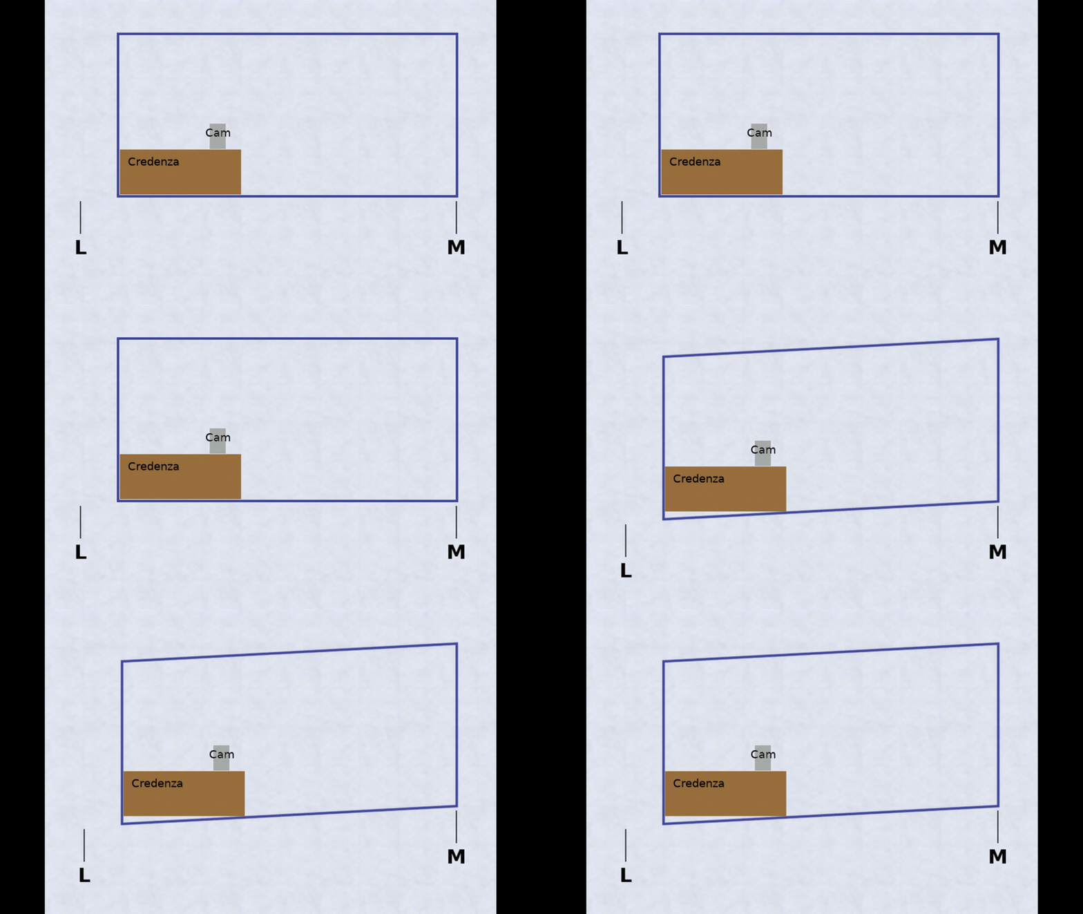
Consider the 2-D plane of the south face of the building. If Column L9.1 (along with K9.1) fails, the slab could hinge along the Line M north/south axis in turn pulling the two failed bays east. The walls remain vertical, while the floor slopes, forming a trapezoid. The credenza, on which the Ring Cam sits, presses against the walls and gets pushed around but remains a level platform for the camera. The credenza appears to be nudged east as triangulation shifts the floor in front of the camera.

If you consider the transverse orientation, a 2-D plane along Line L, similar trapezoidal action occurs. Given the cam footage, I presume the slab punches at Line 8, moving the hinge to Line 4 and pulling the two bays to the north. The credenza remains with its back pressed against the south wall in its original orientation so the camera appears to tilt forward as the south portion of the unit leads the descent.

As I said, in simple terms.


Credenza.03_zoqdfc.gif
 

I applaud your going back and relooking at the data that is available in the public domain and trying to piece together the clues that are there. There is a lot of information in what is available, that perhaps we have not pieced together yet.

It requires a lot of speculation and discussions about details available, and multiple looks from many angles form a diverse group of folks to find the truth and eliminate the red herrings.

For example, I have been thinking about Columns I14 and I14.1 coupled with K13.1, and Column 76, and South Wall damage. The more I look at the existing images, videos and available evidence, I can see things now that I could not see in the beginning.

For example, it looks like I14.1 was a traditional punch shear failure on all sides of column. However, looking at I14 it is clear the East side of column was torn away from column, while perhaps the other sides were more classic punch shear. Then looking at I13.1, it appears the slab tore away from the column on all sides.

Point is there is small details that points us to the direction/flow of the collapse. But no one has taken the time and effort to post all those pieces together that drives the whole story home clearly.

Perhaps because it is a major effort to piece together the complete picture of what is in our minds, especially with all the information that was available, and the fact that a lot of that information disappeared from public access, shortly after the collapse.

A better and more watchable version 2 of video O posted on thread 16

 
zebraso (Mechanical)25 May 22 17:34 said:
... I think "seemed set the stage for" is a mouthful.
Yes! Perhaps too much for them to chew?
We now know that the deck Slumped, weeks before. ( please see my post at Thread 16 17 May 22 15:57)
Also, looking at the photos in the CTS owner submission in their lawsuit against their neighbor, I see the discoloration of the joints in the pavers while construction was taking place next door. I associate this discoloration with Florida Black Algae similar to what I've seen at my parent's near Sarasota. It takes some time for the algae to establish itself, so long before the neighbor's construction? So, I assume the slumping and leaking and puddling has been going on for a long, long time?

SF Charlie
Eng-Tips.com Forum Policies
 
SFCharlie (Computer)(OP) said:
I associate this discoloration with Florida Black Algae

It's funny. Only recently I had a passing thought about the stains. I was thinking about another condition in Florida. The tannins in the soil that are known for turning water ways and lakes dark/brown. I suspect they did not import the planter soil from very far away. Tannin containing water is often referred to as "tea-colored".
 
zebraso (Mechanical)26 May 22 18:28 said:
Tannin containing water is often referred to as "tea-colored".
Yes, another likely source.
The point I was trying to make is that the deck was sagging before the construction next door...


SF Charlie
Eng-Tips.com Forum Policies
 
Is there a standard way to make a maintenance free, waterproof, concrete roof or deck?
Is there something that can be put between two layers of concrete, that will be waterproof and durable?

SF Charlie
Eng-Tips.com Forum Policies
 
Status
Not open for further replies.

Part and Inventory Search

Sponsor