Eng-Tips is the largest engineering community on the Internet

Intelligent Work Forums for Engineering Professionals

Miami Pedestrian Bridge, Part III 99

Status
Not open for further replies.

JStephen

Mechanical
Aug 25, 2004
8,602
0
36
US
"Site management has requested that we limit the length of the other thread by forming a new one. This subject may require III, IV...."
So here's Part III. Please don't post any more in Parts 1 and 2.

Part I thread815-436595
Part II thread815-436699
 
Replies continue below

Recommended for you

Hi All,

Just signed new member. I am an electronics engineer, so other than instrument and cabinet chassis, no structural experience and none with bridges or pre- and post tensioned concrete. I do have an intense interest in engineering disasters as they are virtually always caused by the "holes in the swiss cheese" lining up just so, they typically require a number of failures, and there always seems to be a huge amount of human arrogance and ignorance in play. So while I am not a structures guy, I have about 50 years of common sense engineering that has been hammered into me by various successes, failures, and guys who were at the time older and wiser than me.

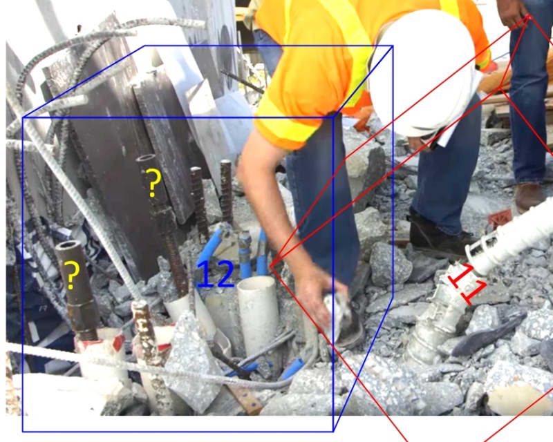
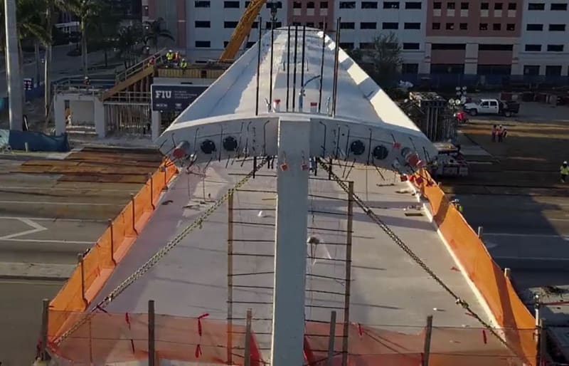
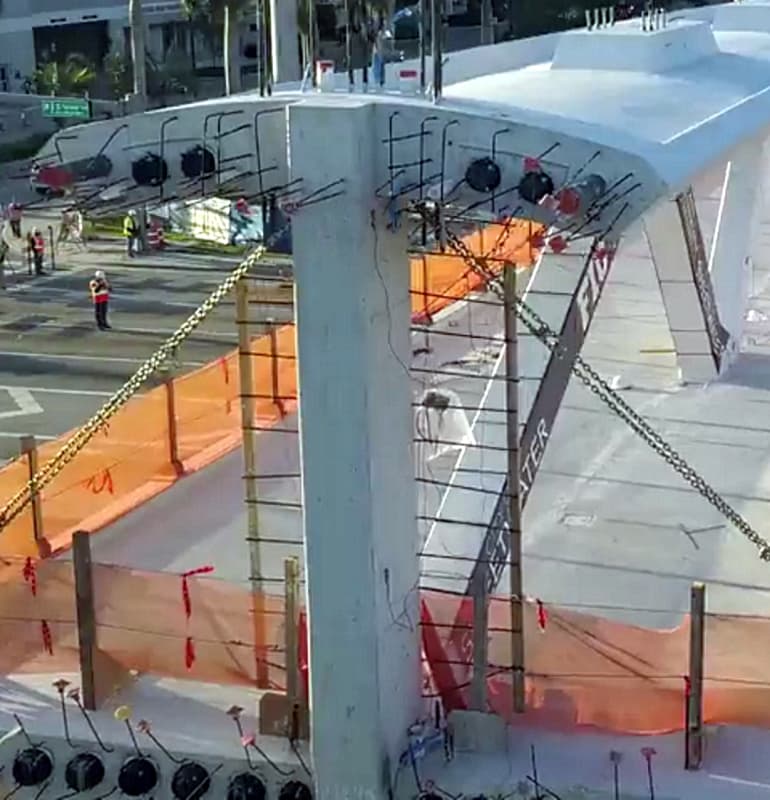
Regarding this specific failure, a number of you have noted that that while trusses 11 and 2 both carry equal loads and that truss 2 had even more compression as it was more horizontally oriented than truss 11, it survived where truss 11 failed. You all got my curiosity up, so I went back to all the pictures to see if there was anything obvious, and while all the line drawings show the trusses of equal beam depth (excuse me if my terminology is incorrect as I am not a structures guy), they are most certainly not. In fact, if you see the picture of truss 2, its depth (not sure correct terminology here) is almost DOUBLE that of truss 11!

In addition to this truss having a much lower load per unit area, it will have greater torsional strength against flexing in the horizontal plane. I think the key though is take a look at how the truss is attached to the deck. As the beam depth is almost twice as great, the attachment to the deck has about double the surface area. Therefore, even if the rebar layout is poor, all the loads, including shear, will be roughly half. Last, this doubling of attachment-to-deck surface area means that the loads are transferred to the deck much further into the middle of the deck where the loads can be more effectively transferred to the deck PT cables.

So, while I believe like many of you that this was a terminally flawed design, impossible to analyze at the micro level at the nodes, blisters, and their respective connections to both chords, and that likely would have failed, possibly later killing dozens, or even hundreds of people, there does seem to be a big problem in that two trusses, both of which are the most heavily loaded trusses in the design, are of dramatically different beam sections. And one has to wonder it that last minute "demand" from FDOT, which added 11 feet to the north end, caused a fatally flawed redesign to an already weak structure.


Gary
 
I don't think anyone has posted this yet:
"Experts cite explosive joint failure as cause of Florida bridge collapse"

Their leading speculation is explosive joint failure at base of #11. Note that in the linked article they have the member numbering off by one relative to the MCM-FIGG drawings, so they refer to the failed member as #10.
 
A number of posters here have noted the awkward path by which compression in number 11 would be transmitted to the tension in the deck's torsion rods/cables.

To the limited extent we can deduce anything from the MCM-FIGG proposal drawing, and the photos posted here, Member #11's lower end pushes against an area of the deck in which forces must work around service channels for the pillar #12, and also travel laterally to the location of the innermost deck tension members. The upper portion of #11's cross section pushes substantially against vertical #12, so those forces create a shear between the base of #12 and the deck, and might meet less resistance.

Summarizing these ideas, compression in the lower end of #11 might look like this figure:

gwfiu_compression_pattern02_iu9nxj.png


Forces distributed very unevenly over the cross section of a member could result in exceeding the member's resistance to bursting in that high compression region. This is a story which could match the newcivilengineer story, linked above.

Much caution is needed though, since it's clear that #11 and its connection to the deck were redesigned after the MCM-FIGG proposal, not least to add the two PT rods (perhaps to accommodate the transporters relocated inboard), and of course the sizeable PT end plates, that must be somewhere in or under the connection.

[Edited to add a comment about SomewhereOverChina's excellent observation]: I agree that there's a concern to have the end diagonals (#2 and #11) somewhat set back from the end of the deck so that transmission of horizontal forces from these members can be distributed to the laterally offset deck tension rods/cables. On the other hand, each of these members also presents a significant downward load, which needs to go directly down through the supporting pillar, and not create sheer in the relatively thin deck, which it would if positioned further set back from the end of the deck.
 
Good eye, SomewhereOverChina. Looking back at it, it certainly looks like several of the members are wider towards the south end, with #2 being the largest change from the initial plans. I wouldn't say they added length to the north end; the north pylon was moved and the overall length of the bridge increased. It is likely they mostly scaled the bridge to keep the same proportions.

I wonder if the root cause was making half-considered changes and not re-doing the stress work. It's like they really wanted to keep the diagonal members as thin as possible and then, for some reason, decided they could not, resulting in the drastic change to #2.
 
I know this is now moot, but I have been wondering about the fake cable stays.
I understand that there can be significant expansion and contraction of cable stays due to temperature changes.
I am thinking about the anchor bolts failing and the deck jumping up about two feet on the bridge up in Canada a while ago.
I would love to hear some comments from the bridge people about the possible issues of expansion and contraction of stays attached to a very rigid structure. Would the stays be stretching in cold weather, sagging in hot weather or both?

Bill
--------------------
"Why not the best?"
Jimmy Carter
 
Continuing to look at the 11-12-deck area, which we know was redesigned relative to the MCM-FIGG proposal docs, looking at this screen cap from an NTSB video, what are the two items I've labeled with a question mark?
gwfiu_base12_01_tcgjd9.jpg


They look to be tension rods, and within the footprint of vertical member #12. But it's not clear to me if they are something that extended vertically into #12, or were actually horizontal and bent up during collapse as the end of the deck fell adjacent to the north supporting column. They seem too inboard to be the most inboard of the deck PT rods/cables, at least as shown on the MCM-FIGG drawings, and seen exposed in photos/videos of the end of the deck.

I'm wondering if they might turn out to be part of a feature to distribute forces from member 11 to the deck.
 
gwideman,

Is it possible that those are tensioners for the future tower that was supposed to support the fake cable stays?

And regarding the same area, does it look like there is no concrete anywhere in that area? None of the tensioners, the plastic conduit, even the rebar. It is almost like that area was purposely voided for some type of service tunnel possibly for the services or other that would have been contained within the cable stay tower. And if that is truly a voided area, then truss 11 and NO SUPPORT to the edge of the deck. It seems a totally open area.

Did they figure when both sides of the bridge were done and the tower constructed that this area would be extremely strong as both truss 11 and its mirror twin on the other side would be in compression against each other? Is it possible the bridge was FEA analyzed as a complete unit? Was the shorter section, with substantially lower forces, supposed to be built first so that truss 11 would have something to work into?

Regarding this link to Civil Engineer:


while I am not a structural engineer, I was not impressed. The author obviously did little or no homework. He did not even have the truss numbers labeled properly, something that has been correct from the first post in this forum, and his "final configuration" analysis shows tension on some of the trusses like they are being supported by real cable stays. Yet if I understand everything I have read correctly, including the original proposal, those stays are almost decorative and may in fact proved more support for the tower as guy wires than as anything to hold up what is a truss bridge (apologies for the true structures guys that make the point that a true truss bridge is always hinge pinned).

This structure seems like a heavy, ugly (I am with Tomfh), costly alternative to a real cable stay bridge, virtually all of which I have seen are quite light, airy, and beautiful looking. Not sure the relative cost of a true cable stay bridge though versus a simple steel passenger bridge.

Gary
 
SomewhereOverChina said:
while I am not a structural engineer, I was not impressed. The author obviously did little or no homework. He did not even have the truss numbers labeled properly, something that has been correct from the first post in this forum, and his "final configuration" analysis shows tension on some of the trusses like they are being supported by real cable stays. Yet if I understand everything I have read correctly, including the original proposal, those stays are almost decorative and may in fact proved more support for the tower as guy wires than as anything to hold up what is a truss bridge (apologies for the true structures guys that make the point that a true truss bridge is always hinge pinned).

Your assessment is correct. While I have not read the link in its entirety, the assumption that this was a cable stayed bridge shows a gross lack of research in the available information. Without the ability to tension the 'cable stays' they will not be under tension in their finished state, except for under transient loads. You can't magically turn a simply supported span into a cable stayed span without adding significant tension to the cable stays.
 
Emba said:
o Dik - just for interest value, on the rescue photo you can see the shirt on the lead person says "FLTF1", that's the "Florida Urban Search and Rescue Task Force 1". Same pic in wider format shows a headlamp on the helmet ( Rear rescuer with dog looks like she has a Sierra cup hanging from her belt. -- Emba

The comment was made because there is a movement within OSHA to replace conventional hardhats with the new style included in the link:


The search and rescue helmets in the photo, likely comply to the new OSHA requirements. These are slowly making their way on to job sites. The new style hardhat is patterned off the helmets that are commonly used for rock climbing. The new OSHA conforming hardhat will likely replace the conventional hardhat; they are safer.

Dik
 
My opinion : At the time of failure the structure where it failed was beyond the elastic range and failed as a brittle material. This is equivalent to reaching the ultimate stress and strain of the material or combination of materials. A concrete cylinder can remain fairly elastic up to the point of failure, steel will remain elastic and continue to stretch i.e. increase strain without increase in load or even with some decrease in load until it ultimately fails.
 
gwideman said:
I don't think anyone has posted this yet:

There have been a couple, as I recall; Eng-tips is generally on top of it:

Structuraleng89, March 18
Tomfh...great video w the dash cam...i see an explosion at the bottom of the vertical at the support...maybe the strand they were pulling at the top of #11 came out at the bearing node of the truss...the tension diagonal adjacent to #11 appears to punch thru at the bottom as well

gte447f, March 18
...it looks like you can make out something shooting up vertically from the top chord first panel point and in the same frame there appears to be an "explosion" of dust at opposite end of diagonal #11

Dik, March 19
A failure at the end of a member may be different than the panel point 'crushing' or 'exploding'.

Rapt, March 20
At the 3 - 4 frame in the video you see something like crushing in this area with an explosion of material upwards from the top (not as in caused by explosives). The diagonals still seem to be intact at this point. Next frame, the top drops very quickly and you get the rotations in the 10/11 node at the top that have been noted previously as the bottom slab at this location crumbles.

Dik
 
dik said:
There have been a couple, as I recall; Eng-tips is generally on top of it

I didn't mean to say nobody on the thread had discussed crushing at various locations.

I meant I thought nobody had yet posted a link to this article. Notable because it's from a site that purports to specialize in civil engineering, though as others have noted, a bit careless in this article.

Hmmm, and now, suddenly, I can't access the article -- it wants me to register.
 
Steve Nuchia said:
@gwideman, Sheet B-8 of the proposal package (linked from thread 1) shows some kind of bolt there but it looks like it's for position-keeping rather than tension.

Sounds plausible, though I don't think the drawing matches the photo. On B8 "CROSS-SECTION", and "SECTION A-A", I see a couple of vertical rods, but they appear outboard of the inboard-most deck tension rods. Then in A-A and C-C there are a couple of horizontal rods at the canopy level to tie the "Main" and (not present) "Backspan" bridge canopies together. So I don't think the rods in question correspond to that drawing.
 
I was wondering why diagonal strut #11 has P.T bars, but it hasn’t P.T bars in the preliminary design.
I found a difference between the preliminary design and reality in transporting the main span. In preliminary design, the shoring supports both ends of that span therefore no need P.T bars in #11.
Maybe they narrowed the distance between two transporters to save money for site clearance, but they paid too much for that.
Temp_pjeflm.jpg
 
If this Oliver McGee is a licensed Professional Engineer he has likely breached the ASCE and NSPE codes of ethics for his unfounded public statements. Might also be a violation of the Texas Engineering law, but I don't know their stance on public statements. In my state, it would be a violation.
 
Leubong,

It has already been well established in earlier threads that there was a significant design change whereby the length of the span increased by 11 ft to allow for a future widening of the road. As such the pillar on the N side moved North into what is currently a grass area. This resulted in a change to the planned movement and location of the transporters further into the span and required the additional PT rods in both member no 2 and 11.

They were both supposed to be released once the span was sitting on the piers.

Now why it then took them 5 days to do it and after they re-opened the road is anyones guess and I would think will form part of the investigation into the collapse.

The PT bars in member 2 were apparently (according to the NTSB) released without incident before they started on member 11.

Please take some time to read parts I and II of this incredibly interesting and thought provoking thread, before re-introducing further items which have already been discussed.

Remember - More details = better answers
Also: If you get a response it's polite to respond to it.
 
Status
Not open for further replies.
Back
Top