Continue to Site

Eng-Tips is the largest engineering community on the Internet

Intelligent Work Forums for Engineering Professionals

  • Congratulations KootK on being selected by the Eng-Tips community for having the most helpful posts in the forums last week. Way to Go!

Miami Pedestrian Bridge, Part IX 33

Status
Not open for further replies.

JAE

Structural
Jun 27, 2000
15,444
A continuation of our discussion of this failure. Best to read the other threads first to avoid rehashing things already discussed.

Part I
thread815-436595

Part II
thread815-436699

Part III
thread815-436802

Part IV
thread815-436924

Part V
thread815-437029

Part VI
thread815-438451

Part VII
thread815-438966

Part VIII
thread815-440072


Check out Eng-Tips Forum's Policies here:
faq731-376
 
Replies continue below

Recommended for you

 
Axial Capacity of Member 11
I don't think anyone has delved into the capacity of member 11 in any detail.
Here is how it compares to member 9 - these are quick numbers - refine them as you see fit.
[pre] Member 11 Member 9
Dimension 24x21 24x21
Length (approx) 27 feet 20 feet scaled from screen
Reinforcing 8 - #7 (7S11) 10 - #7 (7S09) Sheet 8-98
load March 15(AM) 1600 kips est 816 kips est (back of envelope calc) [/pre]

Does it strike anyone as unusual that 11 appears under reinforced if compared to 09?
With twice the load of member 9, 35% more length, and 80 % of the reinforcing of 9?
Does anyone have access to a quick design of these two columns/struts? Use 10% for eccentricity for now. I no longer have access to my RC38 manual, and I don't think it had 8500 psi concrete addressed.
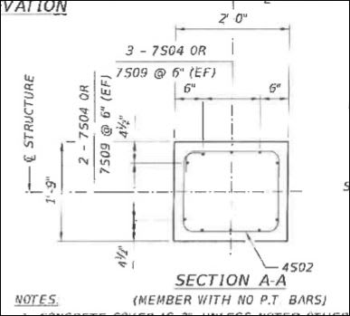
The genesis of this may be in Detail A-A, sheet B-39, which has the note (members with no PT bars). That detail shows 10 - #7 bars. Details with PT bars seem to show 8 - #7 bars.
Temporary PT bars were installed in members 02 and 11 for transportation.
An opportunity for a wrong interpretation? I am not sure 10 bars would been enough - maybe so.
Thanks,


RE: Axial Capacity of Member 11
To pursue an answer to my own question, I found this :
which is a concrete column design/analysis program. It is limited to 5000 psi for concrete strength, however.
First off, if member 11 has only 8-#7 bars, it does not meet the minimum requirement of 1% reinforcing. I assume that is true for AASHTO also. This probably explains why member 09 has more reinf - with no PT bars, it is assumed to be in compression. With PT bars, it is assumed to be in tension, so minimum % reinf does not apply (?).
Checking member 11 I see loads of about 2050 kips design factored. I used 1.25 dead load, 1.35 live load, and a dead weight of 11 kips/ft and live load per foot of 90#X30 ft X 1.35, for a factored axial load of 2050 kips.
Using the Cornell program on-line and inputting 24"x21", 5 ksi conc, 60 ksi steel, and choice "B", Design of Column with Dimensions Assumed - it says we need 32.3 sq in reinf. The area provided by 8-#7 bars is 4.8 sq. in.
Using selection "A", Analysis of Column, same parameters, and inputting 12 - #10 bars, it shows a factored load capacity of 1556 kips.
I realize this is 5 ksi concrete and not 8.5 ksi, but that seems to be a lot more reinforcing than I see on the drawings.
Analyzing the section for 8 - #8 bars yields a capacity of only 1297 kips.
For these conditions the section is woefully under reinforced.
Can someone provide the capacity using 8.5 ksi concrete?
Finally, checking member 09 with 10-#7 bars, the program yields a factored load capacity of 1288 kips, which may work for member 09 when using 8.5 ksi concrete.
Comments?
 
RE: Axial Capacity of Member 11 Continued
In Section A-A, drawing B-39 I do not see ties wrapping/turning around each compression bar. Is this not required in AASHTO?
I see the bars 6" from the sides and the side bars much closer. In looking at the underside of 11, with the PT rod pulled out, I do not see any longitudinal bars and only a single outside tie with its bend maybe 3 inches past the bars at the corners if the detail is correct.
FIU_Sect_AAStrut_htqjbs.jpg

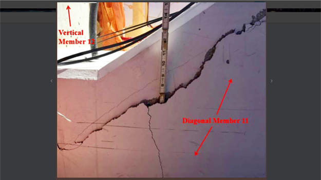
Member 11 was failing up its length.
FIU_b3_khowwc.jpg

Thank you,
 
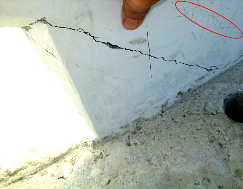
Vance Wiley, since you are examining cracks, here is diagonal crack that appears to have traveled across diaphragm.

DIAPHRAGM-ADJ-TO-12_i6qrcq.jpg
DIAPHRAGM-ADJ-TO-12_LI_l0yw80.jpg
 
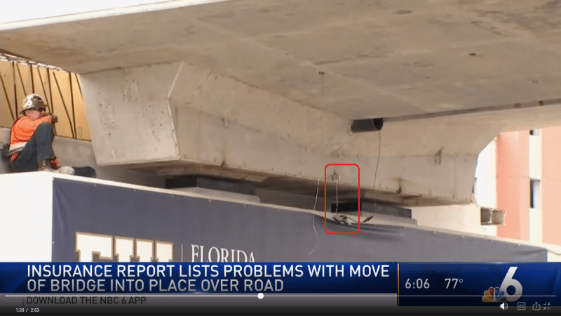
The device I marked here is one of 5 string pots Link used to record/plot vertical displacement (position) vs time.

southpier_ikaz4f.png
 
Vance Wiley said:
In Section A-A, drawing B-39 I do not see ties wrapping/turning around each compression bar. Is this not required in AASHTO?
It is for seismic zones. I don't think it is in FL.

I've pointed this out in the past, the odd detailing of the reinforcement. No longitudinal bars at corner bends?? The J-bars embedded in the slab are just floating there?? Maybe the shop drawings show something different.

And those cracks up 11 could have been following the PT bars, with the PT actively engaged in a last ditch effort at shear resistance.
 
Just a note (see attached file):

Tensioning #2 and #11 cracked #3 and #10 !?!? Did they have any control over this project?


FIU Pedestrian Bridge / BT-904 - Crack Inspection Report

Bolton Perez & Associates, serving as the CEI for the project performed a visual inspection of main span truss members on 02-06-18 after PT bars tendons No 2 and No 11 were stressed. Cracks were found at moment of the inspection. These have been identified per truss member and a consecutive number within the member. The intent is to monitor these cracks after the bridge is fully tensioned and the main span is at the final location.

The members showing these small cracks are truss members that share the same blister at the canopy of the already stressed members No 2 (stressed 1/30/18) & No 11 (stressed 1/29/18) . We believe, this first stressing operation has temporarily created tension on members No 3 & No 10; thus, creating cross sectional cracks transferring the tension loads to the steel on these members. No other truss members within span 1 show any cracks similar to these shown on members No 3 & No 10.
 
 https://files.engineering.com/getfile.aspx?folder=604b1f82-3987-4a54-8f64-030ee6188ede&file=FIU_PEDESTRIAN_BRIDGE_CRACK_INSPECTION.pdf
A few other notes:

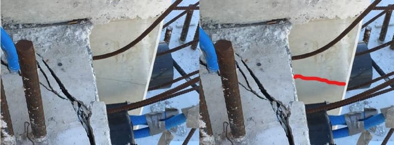
#11 failed early - See attached report. It was posted on the forum earlier and I only know it by its title "CRACKS_REPORT_AFTER_SHORING_REMOVAL", seemingly contradictory to other references as all being well after the shoring was removed. None the less, I refer to Photo #4 and #5 which show a longitudinal crack along #11 proximal toward the centerline of the member and from both sides. Below is a better copy of Photo #4, also taken from somewhere off of this forum. These photos were also revealed in the Preliminary Report as Photo #1 and #2.

11_west_profile_after_shore_removal.2_vkzlst.jpg


I doubt that there is any reasonable explanation to disregard the the nature of this crack. Quite simply, #11 has been racked and will only get worse, and it did!

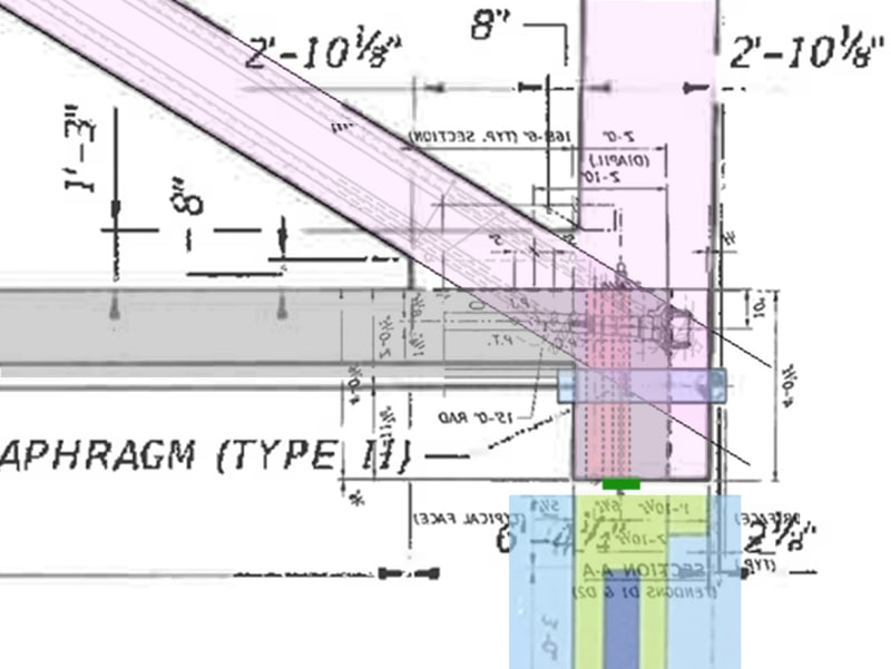
Also, I've taken some liberty with overlays to highlight the issue of vertical forces transmitted from #11 to the shims. They have to wend their way around both the horizontal drain sleeve and the four vertical sleeves. The 11/12/deck node needed all the help it could get and this didn't help.

Deck_11_Overlays.2_lcytos.jpg


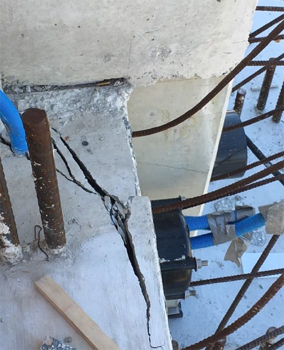
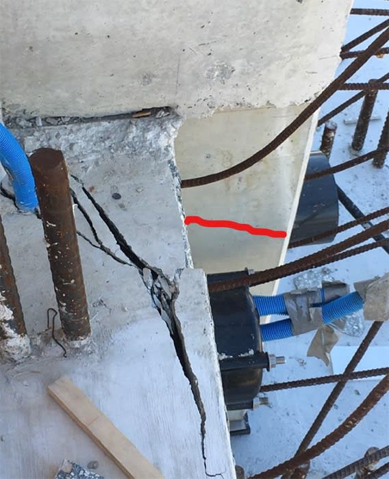
jrs_87 - Yes - that is a breakout forming on the east side of node 11/12. Your photo is remarkably clear and shows perfectly the 8" pipe sleeve thru member 12. That sleeve should have created the formed surface I expected to see in 12 at 20 inches or so below the top of the deck. In looking at the bottom of 12 hanging over the pier,I have not been able to see that formed surface. That suggests the bottom 2 feet or so of 12 is not still attached to member 12.
Have you seen a better photo which shows the sleeve formed opening?
Thanks for the reply.
 
Vance Wiley said:
To pursue an answer to my own question, I found this :
which is a concrete column design/analysis program. It is limited to 5000 psi for concrete strength, however.
Isn't this based on ACI 318-08? Link
Where on P.137 of PDF we have this:
column_w7xgf2.jpg

with phi = 0.65.

Have you been able to locate in the FIGG calcs how they sized the steel for Member 11? The 1% minimum is a baseline.
 
shear3_n0nnjl.jpg


Looks like a classic diagonal shear crack. Imagine rotating Member 12 90-degrees to act as a beam, with the applied load being the horizontal component of force coming from diagonal Member 11.
 
TheGreenLama (Structural)8 Jun 19 11:57

TheGreenLama said:
Imagine rotating Member...

I swear you read my mind. That occurred to me too yesterday, I'm very glad you affirmed it. [bigglasses]

Some other random observations. Figg calculations seem to check if steel in only 12 can contain force from 11(?) We know 12 broke at deck cold joint from photos. We also can guess very base of 12 remained for small period of time as diaphragm slid down pier face since the top inside central edge of pier was chipped out. (Or burst force caused chip before deck moved) (Edit: PT bar more likely cause of chip) I cannot confirm, but In NTSB stills, I see what looks like shattered piece of 8" PVC pipe on deck near PT bar. If so, it got there from being scrapped off by pier.
 
My edited timelapse videos are finally up as a Playlist on the Whirled Gnus YouTube channel.The Playlist and videos are all unlisted so they can't be found by Google search. I didn't add any individual video descriptions - all the details are combined in the lengthy playlist Description. Asmuch as possible, the individual time frames are the identical - all "Move 2" videos start and stop at about the same time, etc. When I get a chance I'll see if I can add links to other relevant non-timelapse videos.
 
jrs_87 - Good catch. And if the 8" pipe was on the deck after the collapse, it was sheared or knocked loose on the way down the face of the pier. That supports the idea that the failure was at the surface of the deck, or mostly so.
It would be so informative if we could see a good photo of the top of the deck at the base of 11 and 12, all swept clean and all debris removed. That will probably be in the final report by NTSB. I think I saw they had cut out that section of deck.
I would like to see the condition of the 4 hoops of reinforcing across the cold joint - designated 7S01 .
 
Well, that didn't take long.... Eng-Tips lurker and YouTube conspiracist Construction Engineering, & EQUILIBRIUM is taking credit for the Whirled Gnus Collapse videos and using them to reinforce his old conspiracy theories and create new ones.

EDIT ADDS:
Went back and added creation details and source information to all video descriptions so the viewer knows how the videos were created, and where the original source video came from.

Reading some of the comments and CE&E's replies - this guy is a real piece of work: repeating disproven rumors as truth, creating outlandish new rumors, and flat out lying.
 
Status
Not open for further replies.

Part and Inventory Search

Sponsor