For what it's worth, here's a member load summary extracted from the LARSA model. The issue with the calculations, however, is that they do not include any results for the construction stage at the time of collapse. As far as I can tell, the LARSA construction check done in the calcs only reflects the span during the move. As a result, the closest state I could find is the "end of construction" (EOC) conditions, which is NOT the load state on the span at the time of collapse.
So, a couple of things to keep in mind:
1) EOC state includes continuity PT, pylon, and faux stays.
2) It's presumed the PT case below excludes the permanent diagonal PT; see note at end.
3) Only two load cases are shown below. Others, such as LL, creep, etc., can be found in calcs.
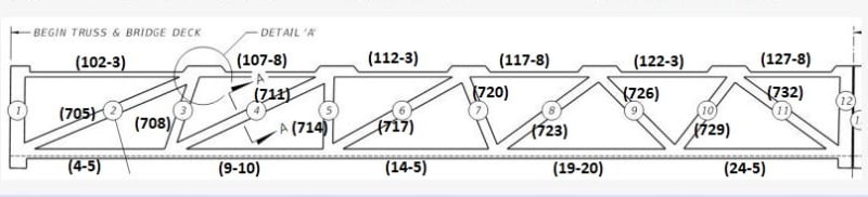
4) A maximum load has been extracted for the LARSA member numbers shown below. These member numbers constitute the bulk of the length for each of the diagonals, top, and bottom chord members. As a result these loads are approximations only.
5) Loads shown are axial only (kips). Bending moments exist, but are not included in this summary. Axial loads are calculated by multiplying the "P/A @ centroid" by member area. If I'm interpreting LARSA output incorrectly please let me know.
6) These are uncombined loads w/o load factors.
7) Negative is compression.
LARSA Members:
Area (canopy) = 16.46 sq ft
Area (deck) = 45.67 sq ft
Area (diag 2) = 5.25 sq ft
Area (diag 3-11) = 3.5 sq ft
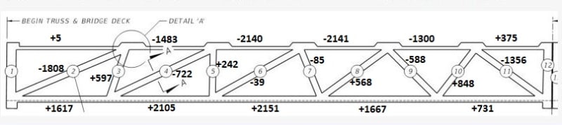
Self Weight Forces (kips):
Chord loads found on pp.579-583, diagonals on p.807 of calcs.
Diagonal 2 components (for 23.88 deg):
Horiz = 1653 k
Vert = 732 k
Diagonal 11 components (for 31.62 deg):
Horiz = 1155 k
Vert = 711 k
Total vertical = 711 + 732 = 1443 k
Rough hand calc of self weight of span based on input areas (excludes blisters and some incidental end zone area of each of the diagonals):
Clear span = 174.83' - 2.83' - 3' = 169' (this will exclude weight from Members 1 & 12 and end diaphragms, which are supported on the bearings)
Self weight of deck + canopy = (45.67 + 16.46) x 169' x 0.15 k/cu ft = 1575 k
Self weight of diagonals:
L2 = 29.1'
L3-11 = 162.8'
Wt = [(29.1 x 5.25) + (162.6 x 3.5)] x 0.15 k/cu ft = 108 k
Total self weight to be carried by truss = 1575 + 108 = 1683 k
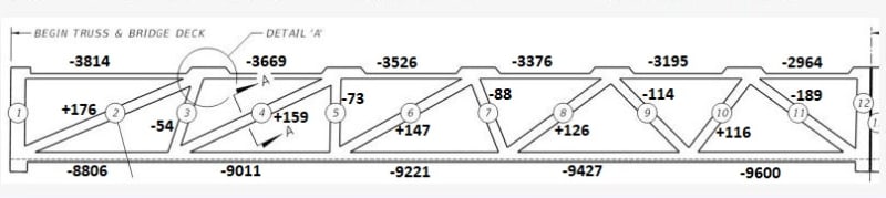
Post-tensioning Forces (kips):
Chord loads found on pp.603-7, diagonals on p.811 of calcs.
Compare with PT stressing forces from design dwg B-69:
Total deck = (835 k x 10) + (527 x 2) = 9404 k
Total canopy (w/o cont.) = (531 + 534) x 2 = 2130 k
Total canopy (incl cont.) = 2130 + (556 x 4) = 4354 k
>>
Note that the two self weight loads, 1443 k for the LARSA model end diagonal forces, and 1683 k for the rough concrete volume, conflict with the 950 x 2 = 1900 k that has been quoted from the first post in this thread. Not sure if it's a result of my approximations, or if it's something else? The 950 tons was reported as the "lift" weight, which would include Members 1 & 12 and end diaphragms and additional 5.83' of span, so that may be where the difference lies.
Also, if you look at say Member 10, PT shows a positive value. This implies that diagonal PT is not included in the LARSA run for PT case shown above. Diagonal PT is sized on p.842 of calcs based on service load combinations, among others, for the critical axial and bending stresses. After having determined this diagonal PT, it's unclear if the model was then rerun to check long term stresses.
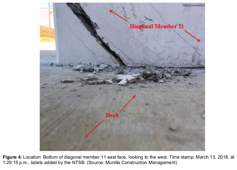
And finally, looking at Member 11 end loads. As Gwideman has pointed out earlier, the values used for calculating the shear reinforcement on p.1283 of calcs (Horiz = 589, Vert = 1233), which were supposedly pulled from the FEA, wildly contradict the loads found in their own complimentary LARSA analysis.