Continue to Site

Eng-Tips is the largest engineering community on the Internet

Intelligent Work Forums for Engineering Professionals

  • Congratulations KootK on being selected by the Eng-Tips community for having the most helpful posts in the forums last week. Way to Go!

Miami Pedestrian Bridge, Part IX 33

Status
Not open for further replies.

JAE

Structural
Jun 27, 2000
15,444
A continuation of our discussion of this failure. Best to read the other threads first to avoid rehashing things already discussed.

Part I
thread815-436595

Part II
thread815-436699

Part III
thread815-436802

Part IV
thread815-436924

Part V
thread815-437029

Part VI
thread815-438451

Part VII
thread815-438966

Part VIII
thread815-440072


Check out Eng-Tips Forum's Policies here:
faq731-376
 
Replies continue below

Recommended for you

jrs_87 said:
Member 11 is offset from diaphragm support. Would areas I marked in orange also be subject to shear? Does anyone know where the steel for this is detailed?

I guess the thinking is that almost any area is subject to shear. The "shear interfaces" looked at in analyses are not necessarily actual physical joints (but could be), but rather just places where the engineer thinks there may be a high level of shear stress, and thus a place to make some calculations. The chosen interface is usually (always?) flat, to make the calculations easy. I would certainly agree that the vertical line you drew would be a good place to analyze. The only drawings I've seen that detail that area are B-60 and B-61, and maybe B24A.

jrs_87 said:
And would not the PT bars have messed with this?

Which PT bars were you thinking? Axial in member 11? Not sure what to think about those.
Longitudinal in the deck? Those are off to the sides of the 11-12-dec connection.
Or maybe the transverse PT bars across the deck? In the drawing you used (from B-61), there are two oval-ish symbols just below the red/yellow line. I believe those are the channels for the transverse PT bars. But this is the only drawing where there's such a transverse PT bar located where your vertical orange line is. Other drawings, for example B-60, omit this endmost PT bar.


gwideman, I agree we should think that shear can express itself almost everywhere. I was just looking at load path of node and diaphragm and it vaguely reminded me of Hyatt hanging rod. But I digress until photos or drawings are released that show exactly where deck and node separated.

I was thinking about temp PT bars in 11. I knew transverse strands pass through node, thanks for telling me about location (ovals). Thanks for your post, I will study it more now...

PS. After watching some lectures I can see how negative values for re bar area are legitimate (assuming the re-bar is placed anyway).
 
jrs_87 said:
PS. After watching some lectures I can see how negative values for re bar area are legitimate (assuming the re-bar is placed anyway).

Really? That's intriguing. Which lecture(s) pertain? BTW, I did look at some of the links you posted previously -- thanks for those.

jrs_87 said:
I knew transverse strands pass through node, thanks for telling me about location (ovals).

... but according to other drawings, that last transverse PT strand is omitted and does not go through that 11-12-deck node. (Which I noted in a previous post would mean that the FIGG "crack meeting" presentation overstates the clamping force on #11's extension through to the end diaphragm.)
 
jrs_87 said:
Member 11 is offset from diaphragm support. Would areas I marked in orange also be subject to shear? Does anyone know where the steel for this is detailed?

It occurs to me that your vertical shear interface might be seen as "safe" immediately as follows:

They are using a coef of friction mu = 1. Since the angle of #11 is less than 45 degrees, the horizontal force, (and thus the friction), must be greater than the vertical force.

And the flipside of this same reasoning is that it would be obvious that for the horizontal shear interface we've been discussing, a significant amount of rebar would be required.
 
gwideman said:
Really? That's intriguing. Which lecture(s) pertain?
(re: negative rebar area)

Sorry, I don't know yet exactly what I saw and where. Perhaps we can get more specific and compare notes later. The NTSB report is months away so plenty of time remains. The idea was iterative adjustments and checks with the primary goal of not making structure stand, but determining how it would fail i.e. provide warning. Figg seems to have used same codes in presentation to present a case structure would not collapse because it passed design checks. But the codes don't mean that exactly. Figg had the warning the code provides but seems to have discounted it.

You may have seen in lectures where, for the sake of simplified equations, steel (in the equation) is replaced with equivalent (more area) concrete. Side point> We have all heard concrete is strong in compression and weak in tension. One Phd said that is wrong, it is weak in both. I'm losing focus and need to take a break for a week or so.
 
gwideman said:
They are using a coef of friction mu = 1. Since the angle of #11 is less than 45 degrees, the horizontal force, (and thus the friction), must be greater than the vertical force

I have to make a point here. Nowhere, absolutely nowhere, in reinforced concrete design does "friction" come into any analysis. Concrete does not provide any frictional resistance. It is not a "thing." You will not find friction mentioned anywhere in any learned treatise on reinforced concrete design. The only structure that can resist shear or tension in a reinforced concrete structure is steel. In this case, no steel was provided to restrain the diagonal #11 from moving to the north (right, in the figure above), away from the tensile force that was trying to develop in the deck cables to move to the left. Those stirrups you see are not long enough to develop any tension load within the concrete, and even if they were long enough, they are totally inadequate in sectional area. This has been demonstrated above.
 
I'm assuming you are discounting the Shear Friction method described in ACI 318 as "not really friction"?

Check out Eng-Tips Forum's Policies here:
faq731-376
 
FortyYearsExperience said:
I have to make a point here. Nowhere, absolutely nowhere, in reinforced concrete design does "friction" come into any analysis.

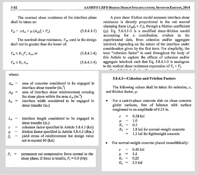
AASHTO LFRD Bridge Design Specs 2014 page 5-82 and following (included as PDF pages 1297 and following of the FIU "Final calculations" PDF):

gw_20190521_aashto_5_82_hzm5kv.png
 
JAE said:
I'm assuming you are discounting the Shear Friction method described in ACI 318 as "not really friction"?

JAE, maybe FortyYearsExpereince is hokie66 :)
 
gwideman said:
the interface length chosen is only 5'-5.8", which includes the entire dashed red line,
Just to finish my thought. This 5.49' is shown on pp.1387 & 1381 of calcs (as 9.598 sq ft or 1382 sq in). It includes both members 11 & 12.
On p.1283 of calcs, the Acv shown in table is only 882 sq in. No "LUSAS View" slice drawing is shown for this. I'm assuming they're referring to the same plane, but here instead of 5.49' they only consider 3.5'.
Thus, missing area would mean missing load. At least that was the thought.
 
gwideman said:
AASHTO LFRD Bridge Design Specs 2014 page 5-82 and following (included as PDF pages 1297 and following of the FIU "Final calculations" PDF):
Precisely. This code tells you how to calculate shear resistance via frictional force transfer between surfaces of steel or concrete that are cast or placed as separate or joined entities AND THEN CLAMPED TOGETHER. By contrast, my point relates to poured concrete reinforced with internal steel rods or cables, like in the bridge that collapsed. Nowhere in the design codes for such reinforced concrete does internal concrete "friction" provide any credit for reducing the amount of steel that must be provided to withstand tensile shear forces within the structure. As you can see, THERE ARE NO CLAIMPING FORCES in this bridge structure (and certainly not in the vicinity of the failure cracks that were observed). So, I am not "discounting the Shear Friction method described in ACI 318 as 'not really friction'." What I am asserting is that in rebar reinforced concrete design (where there are no clamping forces), concrete friction is not a factor for reducing the steel required to withstand tensile shear forces. If in fact the design of the FIU bridge relies on "friction," internal to the concrete poured to make up the bridge, in order to reduce the shear steel requirement, then that would certainly go a long way to explain why it collapsed.
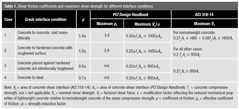
See for example the following table which exemplifies the kinds of interface where it is appropriate to consider friction between opposing surfaces. Category 4 is not rebar reinforced concrete.
concrete_friction_rywygk.jpg
 
FortyYearsExperience said:
See for example the following table which exemplifies the kinds of interface.
Sorry, I'm not clear on the point you are making. Are you saying that this table covers the case of the FIU bridge? (If so, which of the listed Cases apply?)

Or that the table covers cases where friction applies, but that it does not cover the FIU bridge? (If so, why does it not apply?)

Thanks.
 
gwideman said:
I'm not clear on the point you are making.

The table covers cases where friction applies, but it does not cover the relevant part of the FIU bridge because the shear plane that had the highest shear stress in the FIU bridge (namely the condition that is the subject of my 'back of the envelope' calculation above) did not include any clamping force. The mere suggestion that any code permits reliance on a "friction" force supplied by concrete to reduce the tensile shear steel demand in such case is nonsensical.

 
FortyYearsExperience said:
The table covers [...] does not cover the relevant part of the FIU bridge because the shear plane [under discussion here] did not include any clamping force.

As I understand it, the "clamping force" scenario is where the interface is rough to some amplitude, so that if shear is to occur, the mating bumps and valleys would have to ride up on each other, which would create a separation across the interface and thus meet the tension force of the rebars that cross normal to the interface. So the rebars would be designed to supply adequate tension (as oppose to sheer per se), and also must be sufficiently developed. It is that tension that's referred to as "clamping force"

On brief googling, whether or not to add externally applied force as part of the force normal to the interface (resisting the "riding up") is a subject that appears to have developed over the years. For example:

"Examination of shear friction design provisions" [URL unfurl="true"]http://scholarsmine.mst.edu/cgi/viewcontent.cgi?article=8759&context=masters_theses[/url]
... notes:

"The equation for the nominal strength of the interface given in the AASHTO LRFD [2016] provisions is provided in Eq. 2.5. [...] The design for interface shear transfer in the AASHTO LRFD provisions is quite different compared to the ACI 318 code and PCI Design Handbook [...]. Pc accounts for the addition of any normal force that is applied to the interface (compression is taken as positive in the equation). Pc is added to the clamping force, Avf x fy, since both forces are acting normal to the shear interface plane. [...]
Vn = c Acv+ mu ( Avf fy + Pc) (Equation 2.5) "

I'm not versed enough in this discipline to know whether this is good, bad or indifferent. But it does look like it's an accepted idea in some circles, and corresponds to FIGG's calculations, albeit with (I believe) the wrong input numbers.
 

This academic thesis makes it quite clear that the notional "friction" produced in the concrete is a factor that allows for greater shear stresses to be accommodated in the concrete. This analysis is silent on the question of any reduction being allowed in the required tensile/shear steel. As my "back of the envelope" calculations show, the tensile/shear steel provided in the bridge to tie diagonal #11 to the deck was wholly inadequate. About 27 square inches of tie steel was required (absolute minimum). Whereas, 5 square inches of stirrups were provided, and they were not long enough to develop any tension force. The FIU/Figg calculations referred to "friction" in the concrete, but that is irrelevant to the question of required shear steel.
 
FortyYearsExperience said:
minimum steel to tie A to B = 1.45E3 [kips]/53 [kips/sqin] = 27 sqin

Just to clarify for me: This is 27 sqin cross section of the rebar that should be placed perpendicular to the shear interface, right? That being the horizontal shear plane depicted in my 13 May 19 22:48 post ([Part 2] Now for the 11/12/deck analysis from UCPP_Final_Calculations_Superstructure (1).pdf page 1388.), right? If so, I'd like to understand this formula.

The shear interface has to connect the horizontal northward component of the member 11 axial force ultimately to the southward tension of the deck's tension rods. But being perpendicular to those two main forces, that steel is not directly in tension, but rather it would be in tension as a result of the interface trying to separate by the two faces "riding up" over the interlocking bumps and valleys.

So the calculation that involves the main force (your 1.45E3 kips) and the tensile strength of rebar (your 53 kips/sq in) would involve a factor to account for the riding-up mechanism. So I thought (but await your confirmation) that you are using:

Vn = X ( Avf * fy) or solving for minimum steel area: Avf = (1/X) * (Required Vn) / fy

Where:
[ul]
[li]Avf: Area of rebar [sq in], to be found[/li]
[li]Required Vn: 1.45E3 [kips][/li]
[li]fy: 53 [kips/sqin][/li]
[li]X = either mu, or mu * lambda, where various tables show mu and lambda both having values of about 1.[/li]
[/ul]
In short, I'm trying to understand whether you are effectively using the same formula as FIGG, but using only the Avf * fy the term, and assuming X=1, or whether you are using something completely different, or even looking at a different shear plane.
 
gwideman: Shear and rebar. There may be more than one type of shear. One type is diagonal shear in a beam (the term diagonal means in the beam, not that the beam is necessary a diagonal member). An rc beam does not always require steel for shear, but it almost always needs longitudinal bar below neutral axis because concrete opens in tension too soon before it crushes in compression. Diagonal shear reinforcement (stirrups) are aligned at 45 degrees from stress or strain (not sure which) to resist shear.
Now, the type of shear you are looking at for 11/12 is related to resisting beam kick-out. I have no idea how that is quantified, but if the steel is perpendicular that would just be a "dowel effect" for which concrete crushes easily around the thin bars. Rebar is designed to resist tension along it's entire length, hence the rings around the bar. So I would expect some type of diaphragm to be required to resist kick-out. If friction is a factor, it becomes mute when crushing starts (little marbles of crushed concrete).

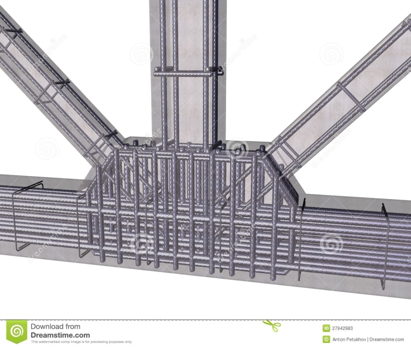
When I first looked at FIU bridge plans, I expected to see something like this:

reinforced-concrete-structure-27942983_tsbdba.jpg
 

From our old youtuber friend in PA.

Audio recording allegedly made of Linda Figg pitching her concept to FIU. Difficult to listen to (excessive grandiose buzz words: award winning, iconic, signature, grand, one-of-a-kind...), but provides hindsight into what went wrong. (I'm not placing any blame on her, that would not be honest and fair at this point, there is more to this story.)
 
gwideman and jrs_87 said:
"There may be more than one type of shear."

Guys, time to get real. Can anyone commenting on this problem explain to me how they applied the concept of Mohr's Circle in resolving the forces that existed on the day of the failure? If you can't, then, really, you will not understand why the bridge collapsed. Evidently, FIGG did not consider this either.

In reality, a "shear" force is only a combination of tensile force and compressive force on a body, in which the angle of orientation of the two principal forces (tensile and compressive) may change at different parts of the body. There is no third force called a "shear" force once all the tension and compression forces are accounted for. Mohr's circle provides a perfect explanation of this principle. In reinforced concrete design, the tensile forces are taken by the reinforcing rods, and the compressive forces are taken by the concrete and the reinforcing rods. In the case of the failure of this bridge, there was effectively zero reinforcing rods to withstand the tensile component of the "shear" force existing between element #11 and the deck. End of story.
 
Hear,hear!
I spoke with Occam's duck and he assured me the guy was a quack, but you can't deny the obvious!
 
Status
Not open for further replies.

Part and Inventory Search

Sponsor