Continue to Site

Eng-Tips is the largest engineering community on the Internet

Intelligent Work Forums for Engineering Professionals

  • Congratulations GregLocock on being selected by the Eng-Tips community for having the most helpful posts in the forums last week. Way to Go!

Miami Pedestrian Bridge, Part IX 33

Status
Not open for further replies.

JAE

Structural
Jun 27, 2000
15,463
A continuation of our discussion of this failure. Best to read the other threads first to avoid rehashing things already discussed.

Part I
thread815-436595

Part II
thread815-436699

Part III
thread815-436802

Part IV
thread815-436924

Part V
thread815-437029

Part VI
thread815-438451

Part VII
thread815-438966

Part VIII
thread815-440072


Check out Eng-Tips Forum's Policies here:
faq731-376
 
Replies continue below

Recommended for you

Gwideman, just as a matter of comparison, if you use the FIGG calc you've shown as a guide to calc the area for node 11/12, and not the hashed area shown in the presentation, the approximate shear area would be:

6.33' L x 2' D = 12.66 SF x 2 sides = 25.32 SF

In this case the conduit area would account for a smaller percentage of total area. Still, I think it would be correct to discount that area.

This is the first I've heard of the calculations being available online. I will have to look at when I get time.

And just a thought on rebar disparities between drawings and presentation. It's possible the shop drawings use different call numbers to identify the bars, and those call numbers are what they're showing in the presentation.
 
TheGreenLama said:
In other words, a tendon at the centerline of the diaphragm would, if it existed, generate twice the stress than one at midspan.

Are you sure about that? If what you say is true, that seems to make the total stress higher than the total force applied by all the transverse tendons.

If there were N tendons, equally spaced X distance apart (with the end ones at X/2 from each end), each applying force F, then the force applied would be NxF, and according to your discussion, the resulting stress would be (N+2) x F.

Or have I fallen into some reasoning trap?
 
Gwideman, Assume distance from edge of deck to centerline is 10', and force from tendons distribute out at 45 deg. Tendon in center of bridge would have force distributed over 20' of deck. Tendon at end of bridge is only distributed over 10' of deck. Assuming same tendon force, stress would double.
 
TheGreenLama said:
Assume distance from edge of deck to centerline is 10', and force from tendons distribute out at 45 deg. Tendon in center of bridge would have force distributed over 20' of deck. Tendon at end of bridge is only distributed over 10' of deck. Assuming same tendon force, stress would double.

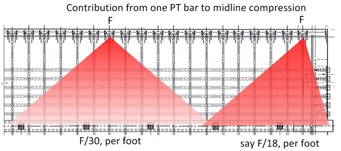
I believe your point is illustrated like this:
gw-effect-of-transverse-PT-03_ce3gvb.jpg


... where this is a considerable simplification in that the forces won't distribute evenly over the entire +/- 45 degrees, and won't stop abruptly at the edge. However, OK for this illustration.

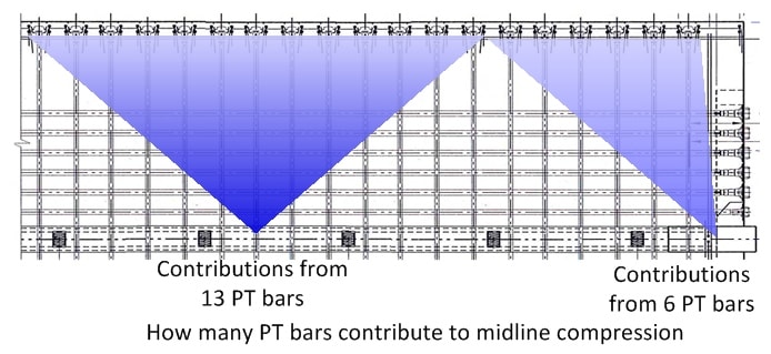
I understand your point, however, in the middle (longitundinally) of the span the midline points are receiving forces from PT bars within +/- 45 degrees, whereas at the end of the span they only receive forces from half that amount of PT bars [*], cancelling out the doubling that you state. Like this:

gw-effect-of-transverse-PT-05_tuhpue.jpg


[* or less in the FIU bridge, due to the non-uniform wider spacing at the end of the deck].

I still might not understand something about this, but this is the way it seems to me.
 
[Edit: A few posts down, IceNine corrects my mistaken impression. The calculations I reference here are not for the endmost strut nodes per se, they are for the end diaphragms transmitting vertical force from those nodes to the support pads under the diaphragms. See later discussion.]

I'm sure everyone is enjoying their Saturday studying the Plans and Calculations docs at [URL unfurl="true"]http://facilities.fiu.edu/projects/BT-904-PRR.htm[/url]

Pursuing further the design of the 11-12-deck area, document UCPP_Final_Calculations_Superstructure Misc Details.pdf presents some calculations.

However, despite this being a "Final" document, the numbers used seem disturbingly at odds with the actual bridge.

End Diaphragm I, PDF page 11

Struts 1 and 2, South end, not the ones that failed
Fc = 1336 kip
alpha s (theta s in the accompanying drawing) = 39 deg, compared to actual angle of strut 2 = 23.9 deg.

End Diaphragm II PDF page 31
Strut 11, North end (the one involved in failure).
Diaphragms II and III are considered together, despite dissimilarities.

Fc = 729 kip (this is half of what's reckoned elsewhere, for example in "the FIGG presentation" PowerPoint.
alpha s (theta s in the accompanying drawing) = 53 deg, compared to actual angle of strut 11 = about 32 deg.

Of course, the actual angles being much smaller in both cases than the ones in the calculations cause the actual forces to be considerably larger than those in the calculations.

There must surely be some later calculations, since these are dated September 2016, and don't seem applicable to the bridge as built.
 
gwideman,

These are strut and tie models of the end diaphragms. Because the centerline of the truss isn't supported with a bearing directly beneath it, the end diaphragm must span between bearings. So the angles in these calculations are the the angle from the centerline of truss to the bearing, not the angle from the truss member to the deck.
 
gwideman said:
this is a considerable simplification in that the forces won't distribute evenly over the entire +/- 45 degrees, and won't stop abruptly at the edge
The distribution does stop abruptly at end of bridge. That's the whole point. Less deck area to capture force means higher stresses.

gwideman said:
whereas at the end of the span they only receive forces from half that amount of PT bars
Yes, but the stress from those bars is higher than at midspan.
 
IceNine said:
These are strut and tie models of the end diaphragms. Because the centerline of the truss isn't supported with a bearing directly beneath it, the end diaphragm must span between bearings. So the angles in these calculations are the the angle from the centerline of truss to the bearing, not the angle from the truss member to the deck.
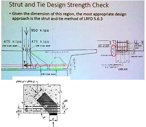
Ah, thanks for that comment, I see you're right. So the calculations in UCPP_Final_Calculations_Superstructure Misc Details.pdf on PDF page 31 and following correspond to the meeting presentation slides thus:

gw-diaphragm-strut-and-tie-01_chvxee.jpg


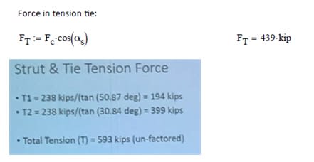
... and the results compare like this:
gw-diaphragm-strut-and-tie-02_t1l8zk.jpg


... with the presentation's unfactored 593 (652 factored) considerably higher than the calculations' value of 439 which appears to be the factored value. This is I guess due to changing from one pad on each side of the support close to center line to two pads each side, somewhat further away, especially the outboard pads, hence more acute angles.

Luckily, the the eight #11 bars anticipated in the calculations (8 x 11S01, drawing B-47) are enough for the load. Though the presentation calculation adds in an additional 2 x 0.31 sq in for a slightly improved result.

Anyhow, this does not seem to be an element that failed, but it does mean I'm still not seeing where in the calculations the connection of #11/12/deck was analyzed.
 
TheGreeLama said:
gwideman said:
this is a considerable simplification in that the forces won't distribute evenly over the entire +/- 45 degrees, and won't stop abruptly at the edge
The distribution does stop abruptly at end of bridge. That's the whole point. Less deck area to capture force means higher stresses.

Perhaps the sentence you quoted was not quite clear. I am saying that for this discussion I accept your simple model of the PT force being distributed over a +/- 45 degree triangle, but I note that the nature of the simplification is that at the bridge midline the force won't actually distribute evenly over the +/-45 degrees, and also won't stop abruptly at the edge of the 45 degrees.

Yes, agreed, the forces will not exit the edge of the concrete, as I diagrammed right before the part you quoted.

Anyhow, the more important part is this:
TheGreeLama said:
gwideman said:
whereas at the end of the span they only receive forces from half that amount of PT bars
Yes, but the stress from those bars is higher than at midspan.

So at this point I think you agree that the two effects I diagrammed are indeed at work. And hopefully that in an "ideal" case where the transverse PT bars are evenly spaced, (so a half-space at the end), the two effects cancel out, resulting in uniform distribution of force to the midline of the bridge, and not an increased distribution of force toward the ends.

The one step further that I take it is that the actual bridge is "missing" the final tendon, so the transverse force at the midline near the end (at the 11/12/deck node) must be reduced.
 
I found a hint about shear with the deck on page 1382 of the calculations report. It refers to "Traction Force location from F.E." which doesn't seem to be mentioned anywhere else. There's something promising on page 1388, but it doesn't track with any force values I've run across.
 
3DDave said:
page 1382 ... page 1388 ... doesn't track with any force values I've run across

I think you are on to something there. I'll try to elaborate.
 
As 3DDave has noted, pages 1382 through 1388 present some calculations that appear to calculate the forces at a horizontal shear plane that more or less matches the leading proposal for that actual failure location. But the numbers in those calculations don't match very well what we think we know about the bridge.

To try and correlate them with other numbers, I will look first at the #1/#2/deck connection, because those calcs almost correlate. Then look at the #11/#12/deck calcs.

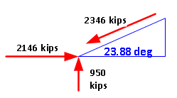
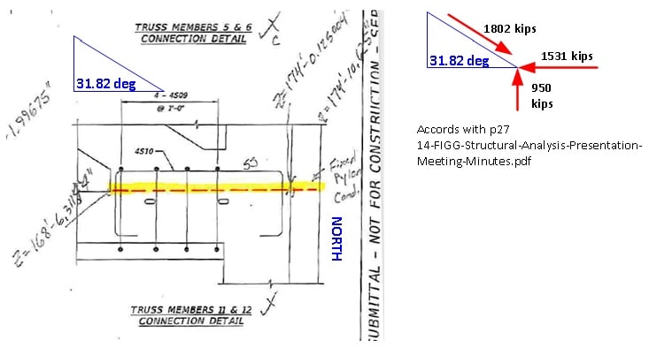
First, here's what the forces should look like at 1/2/deck, I think.
gw-fincalc-01_k74jet.png


These are based on assuming that there's a vertical component of 950 kips, half the weight of the bridge, through each of the end diagonal members. This matches the approach in the "presentation" PowerPoint.

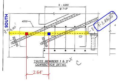
Here's the shear plane referenced in the calcs:
gw-fincalc-02_nsonms.png

(Yellow is in the pdf. Red and blue added by me.)

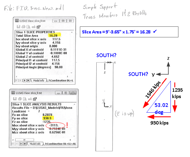
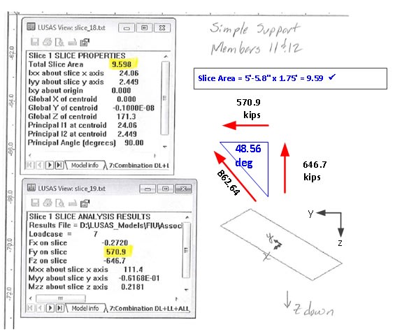
And the analysis results.
gw-fincalc-03_jdv2sk.png

(Yellow is in the pdf. Red and blue added by me.)

No explicit angle is provided. However, I have added a sketch of the vectors from which to infer an angle.
The angle doesn't match what we might expect. But at least the vertical component is more than half the weight of the bridge. Possibly coincidentally, the horizontal component almost matches half the weight of the bridge. But is far less than the horizontal force one would expect from the angle of ~24 deg

A further oddity is the large Mxx value, which I assume is moment around the X axis. This perhaps corresponds to the offset between the center of the shear patch and the supporting column? (The small blue and red squares in the previous figure). 2.6ft x 1235 kips = 3211 ft-kips, very close to Mxx = 3113.

Comments: Very odd that the angle is so unexpectedly tall, but at least it has a vertical component that is in the same range as the half-weight of the bridge. (Though the concern of the analysis is to assess the horizontal component, that looks very understated.) I don't fully understand the analysis, but the force numbers are somewhere near the expected ballpark, if not actually in it.

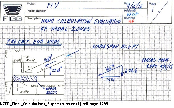
For additional comparison, here's an excerpt from the analysis on page 1299:
gw-fincalc-04.png_bacw0q.jpg


Here again, puzzlingly, the vertical component is significantly less than the half-weight of the bridge.
 
[Part 2] Now for the 11/12/deck analysis from UCPP_Final_Calculations_Superstructure (1).pdf page 1388.

Here's the analysis diagram of the shear plane considered, and the forces involved, based on the assumption that member 11 has to include the vertical force of half the weight of the bridge. (Notably, that assumption accords with page 27 of the FIGG presentation PDF.)

gw-fincalc-10_jzo2w3.jpg

(Yellow is in the pdf. Red and blue added by me.)

Here is the analysis result. Again I have added a vector diagram from which to infer an angle.
gw-fincalc-11_kot6tz.jpg

(Yellow is in the pdf. Red and blue added by me.)

The obvious issues are:
-- The analysis vertical force of 646.7 kips is substantially less than the 950 kips half-weight of the bridge. But oddly similar to the vertical force of 673.6 in the hand-written page 1299 notes.

-- The angle of about 48 degree is far steeper than the actual angle of about 32 degrees.

-- The horizontal force of 570.9 kips is far less than the expected 1531 kips.

These numbers are so extraordinarily different that I would expect someone to jump in and say that I've completely misunderstood the analysis, if it weren't for the results of the #1/#2/deck analysis, which, while still using an unexpected angle, at least had somewhat recognizable sizes of numbers. So I don't know what to conclude.
 
The other puzzle is that there are several areas where the number and spacing stirrups was done to keep the diagonals from rupturing, yet nothing about the amount of re-bar to take the shear loads at these locations.
 
I would like to make a friendly suggestion that any posters that markup calculation drawings and sketches come up with a method to distinguish original and contributed elements. I make this point only because the originals are by nature marked-up already.
 
3DDave said:
The other puzzle is that there are several areas where the number and spacing stirrups was done to keep the diagonals from rupturing, yet nothing about the amount of re-bar to take the shear loads at these locations.

Agreed! There are such calculations of forces and comparison to the quantity of rebar in the calculations for the end diaphragms. Maybe there are some somewhere for the shear plane we're talking about here.

Also, I edited my 1/2/deck post to add a calculation that appears to confirm that the Mxx=3113 is moment attributable to the offset of the center of the shear patch from the support column.

If that's a correct understanding, then the structure would also need to withstand that moment, with appropriate calcs for the concrete and steel. Or the effective shear patch would be considerably smaller and more towards the end of the deck.

A bit of a sidebar at this point though, since it's 11/12/deck that's of most interest.
 
jrs_87 said:
I would like to make a friendly suggestion that any posters that markup calculation drawings and sketches come up with a method to distinguish original and contributed elements. I make this point only because the originals are by nature marked-up already.

Agreed, and good point. For my part I try to add any markup in a distinctive color, usually red or blue. Of course, readers may not be aware that these are my markups, but I also try to reference the original docs, which are readily available, and where the contrast will be obvious.
 
3DDave said:
"Traction Force location from F.E."

The horizontal locations of the south and north edges of each of the shear plane patches are annotated in terms of "Global Z" from the south end of the bridge.

Perhaps the comment you quoted is saying that those Z values came from the F.E. model?
 
I was hoping that if they went to the trouble of mentioning where the force was located that they would mention what the force was.
 
Status
Not open for further replies.

Part and Inventory Search

Sponsor