Continue to Site

Eng-Tips is the largest engineering community on the Internet

Intelligent Work Forums for Engineering Professionals

  • Congratulations GregLocock on being selected by the Eng-Tips community for having the most helpful posts in the forums last week. Way to Go!

Miami Pedestrian Bridge, Part IX 33

Status
Not open for further replies.

JAE

Structural
Jun 27, 2000
15,463
A continuation of our discussion of this failure. Best to read the other threads first to avoid rehashing things already discussed.

Part I
thread815-436595

Part II
thread815-436699

Part III
thread815-436802

Part IV
thread815-436924

Part V
thread815-437029

Part VI
thread815-438451

Part VII
thread815-438966

Part VIII
thread815-440072


Check out Eng-Tips Forum's Policies here:
faq731-376
 
Replies continue below

Recommended for you

I'd appreciate if someone savvy in structural engineering could clarify a few points in the recently-released"FIGG Structural Analysis Presentation Meeting Minutes" document. ([URL unfurl="true"]https://cdn2.fdot.gov/fiu/14-FIGG-Structural-Analysis-Presentation-Meeting-Minutes.pdf[/url]).

1. The doc uses phrases like "capture the nodal zone" (referring to the 11-12 node). What sort of structure does "capture" imply adding?

2. My non-expert reading is that FIGG seemed more concerned with the vertical load causing problems (hence the shim recommendation) than constraining the horizontal load of #11. Is that a reasonable reading?

3. Page 27 gets to the topic of maintaining the connection of the 11-12 node to the deck, so as to be able to "capture the longitudinal force component of the strut"... ie: connect the strut's horizontal force to the deck's longitudinal PT bars. Page 28 shows some accounting of rebars crossing "assumed shear plane". Which plane would this be?

4. Page 29 assesses "nodal shear stability" in a way that might be problematic. If I understand correctly, this looks at transverse forces across the deck, east-west) compressing ("confining") the concrete in the region of the node. It assumes an even distribution of transverse tendons, spaced at 175/65 ft, or 2.7 feet, then applies the force implied to a 4.75-ft "side" of the region of interest. This 4.75 ft is presumably the length of the oblique connection of #11 to the deck.

However drawings such as this one: [URL unfurl="true"]https://cdn2.fdot.gov/fiu/13-Denney-Pate-signed-and-sealed-FIU-bridge-construction-plans.pdf[/url] page 69 appear to show that there are no transverse tendons (or at most 1) in the end region of the deck or diaphragm, the first one coming at something like 3ft 8in from the end (on the plan view), or maybe 4ft 5in (View B-B), or maybe 4ft (page 71, view B-B) or maybe 4ft 2.5in (page 85).

So it seems to me that not only were there either zero or just one horizontal tendons in this area, but they were not distributed evenly over the area of interest, with the compression effect tapering off rapidly toward the endmost region of the deck where the longitudinal force (and its horizontal component) would be most focused. Certainly there will be some compression from the endmost transverse tendon, and diminishing amounts from the second, third etc, but the compression won't be in a strictly transverse direction.

Am I reading this right?

5. The FEA graphics on pages 36 through 43 I think treat the members as homogeneous objects, and led to the conclusion "the spalled areas have not been replicated by the engineering analysis" (page 44). As it turns out, I guess this is a reminder that if the analysis doesn't predict what is actually happening, then the analysis is wrong. Presumably one or more of the actual members were no longer functioning as homogeneous objects, but instead had internal cracks severe enough to require a more complex model for analysis.
 
The release by FDOT of this meeting record, presumably as recorded by the FIU attendees, is useful in showing the frame of mind of the participants, in particular the FIGG engineers. They were under pressure for sure, but had absolute faith in the correctness of their design. That faith was woefully misplaced, at the expense of a number of lives lost.

The NTSB is taking its time in doing this investigation. I just hope that they don't just focus on the immediate locus of where the truss/frame failed, but rather on the whole flawed concept.

 
gwideman, here are my thoughts.

1) "Capture the nodal zone" is an odd phrase. Took me a while to comprehend. Because this is a concrete truss, and thus unique, I think they were reaching for terms to help them in their discussions, and analysis. Maybe capture means how best to capture the behavior of the truss.

2) Yes.

3) Force here, best I can tell, is the axial force in diagonal. Shear plane is that shaded area on page 27. And there are two areas, one on either side of outside faces of diagonal extending into deck and diaphragm. And it should be noted here that with the slope of the diagonal, the horizontal component of diagonal force will be LARGER than the verticl component.

4) Once transverse PT is stressed and grouted the force cone will tend to evenly distribute across the deck, reaching a uniform distribution near the centerline of the bridge. You are right to question conditions at end of bridge. Here, transverse PT stresses would be expected to lessen. How much is open to discussion.

5) I think your take on the FEM is a good one. Concrete with large cracks should NOT be modeled homogeneously.
 
TheGreenLama said:
Shear plane is that shaded area on page 27.

Ah, that makes sense, thanks.

And interestingly, that same figure shows the arrangement of transverse tendons, somewhat speaking to my question 4 about transverse forces containing the region where the axial forces of #11 are "captured". That endmost transverse tendon does not seem ideally placed to help, though it's not clear whether this drawing is to scale.

TheGreenLama said:
You are right to question conditions at end of bridge
And on that topic, page 29 shows a calculation resulting in 520kips of confinement force. But that would be for a region of the bridge that has transverse tendons both north and south of it, and at 2.7ft spacing. Since the region of node 11-12 has only a tendon to the south, and only at the edge of this region of 3 or 4 feet length, I would guess that the actual confinement force resulting from the tendon would be reduced by a factor of at least three of four, so more like 130 to 170kips.

Following this to page 31, this would make the (Phi)(Vni) (without c) = (1908 + 1.4 x 130) x 0.9 = 1881
Which is less than the (page 32) factored Demand Nodal Shear of 1983.

This is a relative pessimistic version of the calculation, but it doesn't look encouraging.
 

Want to emphasize this isn't a truss; truss members only carry axial force and nodes do not carry moment. For this concept, the open web members have to carry moment, shear, and axial force, and the nodes have to restrain these forces.

And therein lies the rub. The design itself was very ambitious. How they would practically design a giant, simply-supported, all-concrete I-beam relying on frame action between the angled "web" members and the top and bottom flange is beyond me. I truly wonder if there was ever a sound way to pull this concept off. If they wanted concrete so badly, a solid web would have made more sense.
 
"...if the analysis doesn't predict what is actually happening, then the analysis is wrong."

BINGO! I think you hit on the crux of the failure to anticipate the imminent collapse of the bridge, gwideman.
 
The question now is this - will claiming total incompetence at understanding the mechanics of the failure with direct observation of the failure be enough for a manslaughter conviction for certain engineers at FIGG and the other companies or will it be a shrug that mistakes were made? How could they see the horizontal displacement at the bottom of 11 and the spalling of the faces and conclude the shims on the pylon were the problem?

I think the meeting notes hint that they knew what was really wrong and they were trying to cover for it when they indicated a desire to tie 11-12 back to the 9-10 node with steel channel until the backspan and pylon were finished; the "capture" mention in the notes.

Questions & Answers
CEI to FIGG: Do we need temporary shoring?
o FIGG responded that it was not necessary. Rather than carry weight, carry load off that number/node. Steel channels to 10/9 node & PT Bars to capture some of that force which is better than vertical support. The diagonal member is what needs to be captured


I think they believed the reapplication of post tension would pull the end of 11 back somehow and that the steel channels would be better than putting cribbing under the bridge as cribbing would make the failure plain to everyone.
 
3DDave said:
tie 11-12 back to the 9-10 node
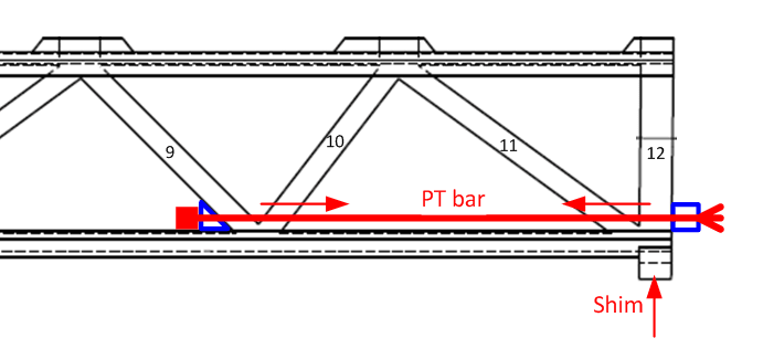
Ah, I had seen "Steel channels to 10/9 node & PT Bars to capture some of that force which is better than vertical support.", but had misunderstood that this was addressing some separate issue they had with 10/9. Your answer filled in that this means channels/PT bars FROM 11/12 TO 10/9. So something like this sketch, which also includes the proposed shim in the gap left directly under 11/12:

capture_11_12_a_fkostu.png


And "which is better than vertical support", because just supporting near the end of bridge, doesn't deal with the fact that, as a truss, the top member is in compression, which needs to be resisted by the horizontal component of compression of 11. So plausible vertical support would need to have been inboard, say under 9/10 like when the bridge was moved. And that would block traffic, and might require yet more calculations unless the other support used during moving was also put in place.
 
Want to emphasize this isn't a truss; truss members only carry axial force and nodes do not carry moment.
Tell that to a Vierendeel truss.


Check out Eng-Tips Forum's Policies here:
faq731-376
 
Many of the comments here deal only with axial forces, which mirrors the problem with the design concept. As samwise753 described above, this was a concrete frame. The Vierendeel action of the frame was not adequately considered.

But it is worse than that...the internal restraint stresses were apparently not well thought out either.
 
Looks like I was typing at the same time as JAE was posting.
 
About "comments here deal only with axial forces" and "Vierendeel" action, and "this isn't a truss".

Clarification please: Are you guys saying that the FIU bridge structure is being discussed here (and perhaps designed) as though it was a truss, but in fact lacks the compliance at joints to be considered as such; that the concrete joints will attempt to resist rotations (as in Vierendeel designs), but not being appropriate to do so will be damaged under certain conditions?
 
hoki66 said:
But it is worse than that...the internal restraint stresses were apparently not well thought out either.

At some level the 11/12 failure appears to be insufficient ability to transmit axial forces to the deck's longitudinal PT bars. Those tendons are positioned in a way that they won't do much to support the deck by itself, so their main objective is to resist the horizontal tension "of a truss's lower members", a substantial amount of it imparted by the two end diagonal members.

Evidently 11 was supposed to transmit the horizontal component of its axial force across the end diaphragm to the PT bars (and the vertical component across the diaphragm to the support pads which were not directly under 11/12).

Has any documentation been released on diaphragm structure, and how 11/12 was connected to it? To what extent does it rely on the integrity of the concrete (possibly damaged by one or another effect, such as rotation of the joint during transportation), as opposed to the capability of the rebar unaided?

(And I note that this ties in to my comment a couple of posts ago that the confinement force for this area seems to have been calculated based on an unrealistic contribution from the transverse tendons, at least for the March 15 2018 meeting.)
 
Not the way I would have said it, but yes, this bridge was a frame, and the members and joints needed to take a lot of bending moment, which I don't believe was adequately considered. Rigid joints in concrete are not easily achieved, in fact never achieved 100%. And the other issue I have raised numerous times was about the internal restraints. Understand that problem?
 
Yes, agree with hokie66.

The "truss" as it was, had all diagonal members and thus - stable triangular shapes along its length.

For most historical truss design (with steel) engineers traditionally assumed that there would be a bit of give in the diagonal end connections, or that if you ignored the fixity at the diagonal ends, there would be some slight inelastic response that would allow you to assume the diagonal ends were moment free (pinned). This also simplified analysis prior to our handy PC's.

However, with this "truss", there was true fixity and the ability of the diagonal ends to be axially connected to the decks depended on the integrity of the diagonal-to-deck connection, which appeared to have been significantly compromised by non-uniform shears though the deck....due to moment perhaps.

Check out Eng-Tips Forum's Policies here:
faq731-376
 
This structure was unique, in the history of the world. Sure, it was built with concrete and steel reinforcement, but the conceptual form was unique. And there was no testing of the concept. No matter how clever or innovative it was thought to be, it was illogical to jump headfirst into this concept without any physical testing. In my previously expressed opinion, that testing should have been load testing of the actual frame while it was still at the casting location.
 
Touche, JAE. I didn't remember a Vierendeel Truss, though it is a truss in name only.

Well said, hokie66. Rigid joints with members at odd angles was just crazy.
 
From the presentation, they relied on shear friction to tie the members together. Not sure if their computations or the actual details comply with accepted practice, but if so, then the whole concept of shear friction would need reexamination. We have had lots of arguments in the structural forums about shear friction theory, and I for one have not accepted its validity.
 
gwideman said:
At some level the 11/12 failure appears to be insufficient ability to transmit axial forces to the deck's longitudinal PT bars. Those tendons are positioned in a way that they won't do much to support the deck by itself, so their main objective is to resist the horizontal tension "of a truss's lower members", a substantial amount of it imparted by the two end diagonal members.

I would say, "all of it imparted by the two end diagonal members."

Here's a thought experiment. Look at member 11 as a column framing into a slab. If member 11 was vertical we would check the "punching shear" capacity of the slab for the axial load in the column, similar to what was done in the recent FIGG presentation. And assuming no moments were in the column, only nominal longitudinal steel would be required. But once the column enters the slab at an angle, as is our case, longitudinal steel from member 11 is going to be required to get the axial load into the slab (and thus the longitudinal PT). That's what's so puzzling about the FIGG presentation. Why didn't they also run numbers for the horizontal component of member 11? They've also failed to detail hairpins tying member 12 back into the slab. So is this a case of people at FIGG not seeing beyond a FEM model?
 
hokie66 said:
this bridge was a frame

Ahem, just now catching on that "frame" has a technical meaning that distinguishes it from "truss", in that frames have joints that can transfer moments (resist rotation), whereas in a truss the members are considered to be pinned, and this able to rotate (at least a little) at the joints, conveying only axial forces.

So if I understand the discussion properly, the idea is that the FIU bridge could work fine as a truss, say made of steel, where some (small) amount of rotation at the joints would be acceptable. Or with steel some or all joints could be made rigid, and achieve some joint-bending-resistance frame properties. But implemented in concrete+rebar, significant trussly bending at the joints would cause damage, and framesque resistance to bending would be difficult to implement.

hokie66 said:
And the other issue I have raised numerous times was about the internal restraints. Understand that problem?

By "internal restraints" are you referring to (competing) forces/moments operating within the concrete in the 11/12/diaphragm region that could cause internal cracking, for example during concrete curing and shrinkage, or loading?

And that would shed light on whether or how the concrete would maintain its integrity and be able to perform, with the rebar, as simple homogenous components?

Are there docs which bear on this?
 
Status
Not open for further replies.

Part and Inventory Search

Sponsor