Continue to Site

Eng-Tips is the largest engineering community on the Internet

Intelligent Work Forums for Engineering Professionals

  • Congratulations GregLocock on being selected by the Eng-Tips community for having the most helpful posts in the forums last week. Way to Go!

Miami Pedestrian Bridge, Part IX 33

Status
Not open for further replies.

JAE

Structural
Jun 27, 2000
15,463
A continuation of our discussion of this failure. Best to read the other threads first to avoid rehashing things already discussed.

Part I
thread815-436595

Part II
thread815-436699

Part III
thread815-436802

Part IV
thread815-436924

Part V
thread815-437029

Part VI
thread815-438451

Part VII
thread815-438966

Part VIII
thread815-440072


Check out Eng-Tips Forum's Policies here:
faq731-376
 
Replies continue below

Recommended for you

The pessimist in me says they were clearly understanding the horizontal shear failure and that's why they wanted to tie back to 9/10 with the steel channels until they could cast in place a stop in the form of the other span and the pylon.

FIGG's is the presentation I would make if I wanted to point the audience in a different direction from the actual failure; however it seems like anyone who did the FEA should have been smart enough to realize the fundamental flaw and not provide anything else that could be used to distract.

However if I did understand the true failure mode the last thing I would authorize is retensioning the PT bars in 11. So I don't know how Pate got himself to that presentation, except brutal ignorance. He knows 11 and 12 are sliding out, has a plan to stop them from sliding out, yet has no grasp on how the are sliding out. And, apparently, neither does anyone else in the room or about to apply the hydraulic jacks to the PT bars.

I think the critical question that might have worked is - why aren't they sliding any faster? That brings focus to the re-bar and from there the loads that have to be acting on the re-bar, which should produce a free-body diagram showing that the diagonals are not actually tied to the deck except by the re-bar; which the PT bars cross. If they had put extensiometers across the cracks in the direction of the movement they would have been able to get a feel for if the failure was speeding up or slowing down and therefore if the re-bar or re-bar anchorage was failing or the re-bar was aligning itself to better resist the load.

In the meantime someone would certainly have called for at least one crawler to come back and shore up the bridge since all it would take for a cascade catastrophic failure is one strand of re-bar to give and transfer it's load to all the others, zippering though them in quick order.
 
gwideman,
That's the gist of it. The various members of the bridge wanted to change volume at different rates and at different times. Therefore, shortening due to shrinkage and prestress, as well as perhaps temperature, would have meant that the web members were acting as struts to prevent the shortening of the decks. Restrained shortening places concrete in tension, and it cracks. But this structure was never "homogeneous", as it was cast bit by bit.
 
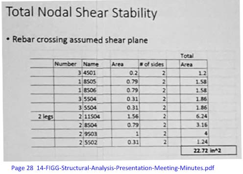
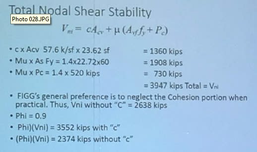
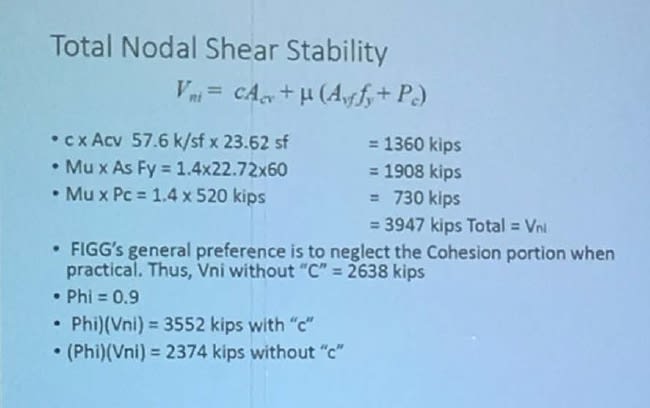
I have atttempted to recreate the "total nodal shear stability" accounting on page 28 (and following) of the FIGG presentation
The table lists "Rebar crossing assumed shear plane", where the "assumed shear plane" is that which is important in conveying the axial force of member 11 to the deck's longitudinal tendons.

I have cross-referenced the listed bars to the rebar list and detail drawings in
Some of these rebars don't appear to me to cross the shear plane.

From page 28:
gw-total-nodal-shear-stability-rebar_lwd0v7.jpg


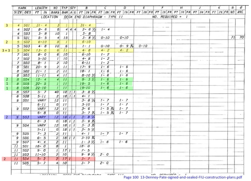
Correlated to the rebar list, and color coded by diameter:
gw-1112-shear-rebar-list_fxygjg.jpg


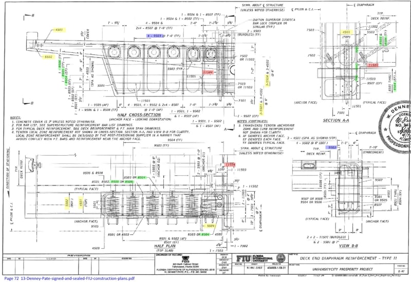
My attempt to find them on the construction drawings. For a larger version see the attachments. Likely you'll need to look at the PDF to see the shape and extent of the rebars in detail.
gw-diaphragm-reinforcement_jnl0ol.jpg


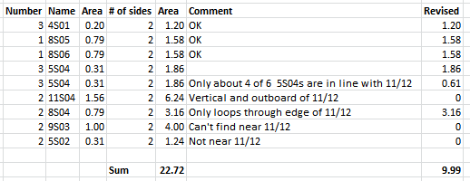
And here are my comments on each rebar line:
gw-total-nodal-shear-stability-recalc_x1zmhw.png


In short, of the 22.72 in^2 called out in the presentation, I only found 9.99 in^2. Have I missed something here? Perhaps these were not the final construction drawings?

Now considering the calculation on page 31:
gw-total-nodal-shear-stability_calc_smygof.jpg


...I commented before that the Mu x Pc component looks overestimated by a factor of three or four due to the geometry relative to the endmost transverse tendon. Now the accounting of the rebars crossing the shear plane(s) looks to be about only 40% of what the presentation counts.

That line of thinking would lead to total Vni being mostly dependent on the Cohesion portion, and without that, significantly less than the factored Demand Nodal Shear of 1983 kips (page 32).
 
gwideman said:
Perhaps these were not the final construction drawings?
Even though these were 100% sealed, there must have been later construction drawings, because these do not show the span shifted to the north, with the pylon base in the SFWMD canal. I am not an engineer but rather know waters well, and I've always wondered about how the shift affected the stability of the north end, considering that a new retaining wall and fill were needed; previously spec'ed concrete piles were now used in the canal instead of on the bank; and whether dredging in that canal location (which was occurring during construction) had any effect. The shift was dictated by FDOT in October, so it's weird that plans signed in December still show the pylon on dry land.
 
Oh sorry, those were the April plans, not the December ones. Maybe they did show the shift?
 
Gwideman, For the transverse PT, they're not talking about how many PT tendons run thru the diaphragm. They're talking about the stress the transverse PT generates along the centerline. And for this you need to consider all the PT. Say you conservatively assume a stress cone extending out at 45 deg. from each anchorage, and the spacing of anchors is 2' - 8". That means that only in the outer 2' - 8" of the deck is there a reduced stress. Looking at the drawings again, the first transverse PT comes in 4' - 0" from the end, and then the 2' - 8" spacing begins (Dwg B-60). Based on this, I think I'd like to modify what I told you earlier about forces lessening near the end. I think that for the purposes of what FIGG is attempting to demonstrate in that calc, using a 54.8 k/ft as an approximation of the transverse tendon force along the centerline is OK.

As far as whether these are the final drawings, the answer is no. There are shop drawings, which are prepared by the mild reinforcement provider, and reviewed by the designer, which detail exactly size and placement of steel. Since these are created based on the design drawings, they're generally identical. But we don't have these. Then, once the bridge is finished, an as-built set of drawings is usually created, which includes any modifications that were made to the original design plans during construction. We don't fully know what these are either.

Lacking shop drawings is one reason I refrained from delving into that very crowded area of the diaphragm. Not sure I want to try and tackle it without them.

3DDave said:
FIGG's is the presentation I would make if I wanted to point the audience in a different direction from the actual failure; however it seems like anyone who did the FEA should have been smart enough to realize the fundamental flaw and not provide anything else that could be used to distract.
Misdirection--that's something I hadn't considered. FIU, the owner, was an attendee. 3DDave, you may be on to something.
 
GreenLama - I want to clarify that it's very likely that Pate & Co initially mislead themselves, the presentation was a continuation of that process; before this presentation they'd already set the PT crew do exactly what would increase the forces in the direction of failure.

I said a similar thing for the failure of MCAS - it all started with a convincing presentation. This follows that pattern.

Gawd how I hate PowerPoint. It's like people switch off their brains when they make them and when they watch them. Just because it's on a screen does not mean it's true. Make a real report, unroll actual blue-prints. Put an actual pencil to actual paper. Convene at the failure site.
 
Power_Point_hfhrdo.jpg


Check out Eng-Tips Forum's Policies here:
faq731-376
 
TheGreenLama said:
For the transverse PT, they're not talking about how many PT tendons run thru the diaphragm. They're talking about the stress the transverse PT generates along the centerline.

Yes, exactly, that's what I was talking about with relation to the Mu x Pc component of the overall page 31 calc.

I don't know the theory that governs how the transverse tendon tension translates into a distribution of compression at the (longitudinal) midline of the bridge. However, my naive assumption is that away from the ends of the span, each point at the midline receives a sum of forces from the transverse tendons to its north and south, most from the closest tendons, and diminishing force from those further away. The further away the tendon, the more those forces are not perpendicular to midline, but the north-south components of the numerous contributions will cancel.

So it's as though each 2ft-8in section of bridge is compressed by one tendon; each tendon serving 1ft-4in region to its south and to its north. Construction drawings show tendon force after tensioning of about 160 kips, distributed over 2.7ft = 59 kips/ft, pretty good agreement with the presentation's value of 54.8.

But the end of the deck is only adjacent to a tendon to its south, with obviously no tendons to its north. So, again naively, that last region of 4ft is covered primarily by "one side" of the last tendon, and no tendons to the north. So the force that the tendon would normally apply to 1ft 4in of midline is instead distributed to 4ft, resulting in only one third the compressive force per unit length.

Clearly this is simplistic. No doubt the material complies somewhat to redistribute the forces a bit more evenly. But I am fairly convinced that the end region can't be seeing the same compressive force (from the transverse tendons) as a region in the middle of the span.
 
Since the failure did not happen within the material of the deck and there is not a good way to generate 1.5 Million pounds of resistance with transverse containment in this configuration, it's a moot point as to what the effect is.
 
3DDave said:
it's a moot point as to what the effect is
I infer you're responding to my post, inquiring into the effect the transverse tendons would have in the region of 11/12?
It may be moot if one's position is that this was a flawed design from basic principles, no need to analyze the details to get to that conclusion. Fair enough.

However, it's not moot in trying to understand FIGG's reasoning. As you pointed out "it's very likely that Pate & Co initially mislead themselves". I think it is valuable to understand how engineers (or management, or whoever) gets into that position. In this case, were these qualitative mistakes (wrong type of structure for the job), or errors of magnitude (should have been 50% beefier), or of construction (drawing said X, but Y got built) and so on.

The recently-released presentation gives a little insight into the model they were using to analyze the 11-12 connection, and the numbers they were plugging into it. Was that a sensible model? Did those numbers properly apply to what was built (or at least drawn)?

3DDave said:
the failure did not happen within the material of the deck
I'm not quite sure what you mean here. I think one of the prominent theories in this forum is that the failure did involved the intersection of deck and 11/12, with pictures before the collapse showing significant spalling of the deck surface adjacent to 11/12. Granted that was not the only spalling, and this is not the only theory, of course.

 
Third post in a series looking at the FIGG presentation Total Nodal Shear Stability calculations, page 23. This time, the Cohesion contribution.

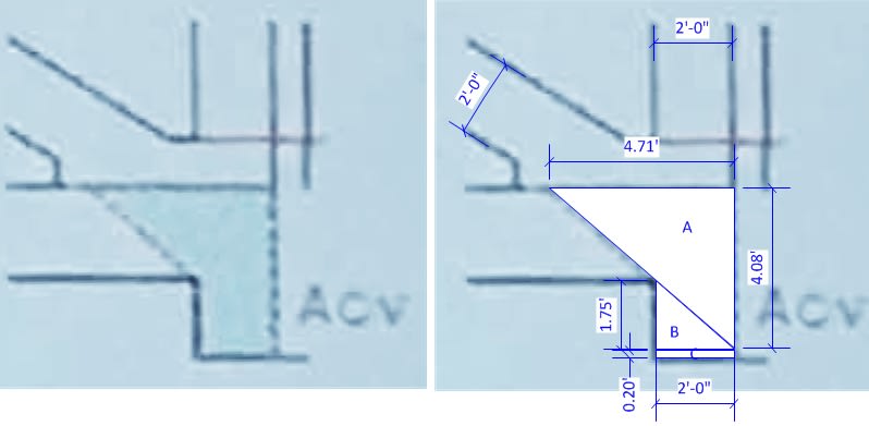
The cohesion contribution is based on a shear plane area of 23.62 sqft, which is the shaded area on page 27. Here's how that number is arrived at:

gw-shear-plane-01_zgrcsu.jpg


Code:
A:  2 x 1/2 x 4.71 x 4.08 = 19.2
B:  2 x 1/2 x 1.75 x 2    =  3.5
C:  2 x        0.2 x 2    =  0.8
                    Total = 23.5168
, which agrees with the presentation (23.6).

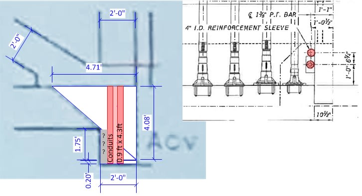
However, that shear area is interrupted by two sleeves (around vertical reinforcing bars). These are shown in this figure:

gw-shear-plane-02_qaqt3l.jpg


The sleeves are each 4 inches in diameter, and have an intervening gap of 2.75 inches (lighter pink), which I think would not contribute to any shear force. So I suggest that the entire 0.9ft x 4.3 ft should be discounted from the shear plane area. (I have also marked a gray "???" area that I think also would not provide useful shear force, but I did not deduct it from the area).

Revised shear plane area: 23.6 - (2 x 4.3 x 0.9) = 23.6 - 7.7 = 15.9 sq ft.
Revised as percent of presentation = 15.9/23.6 = 67%


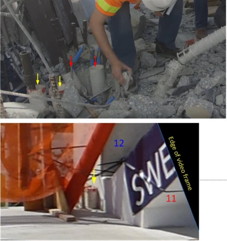
For orientation, here is the area under discussion. The sleeves marked with yellow arrows in the top picture are the ones also shown in the bottom picture. The sleeves marked with red arrows are on the other side of 12, and protruded from the deck only a couple of inches (as other pictures elsewhere in this thread show).

gw-shear-plane-conduit-01_vhf6pl.jpg


Shearing (or at least lack of cohesion) looks to have occurred around and between the sleeves. (Though this doesn't necessarily imply that this was the very initial part of the failure.)
 
The intersection, not the embedment. Since 11/12 weren't actually captured in the deck pour they could not be retained by the deck no matter what. Only the re-bar crossing that boundary could be captured and it looks like the portion in the deck remained there when the rest was sheared off. There's no reason to believe that the few bits of re-bar at the deck edge which carried the loads that spalled the deck could have been reinforced enough to make a difference considering that there were about 26 sections of re-bar joining the deck to the truss at that location; sections that all failed.
 
I'm glad new information is available now. Hopefully soon we will have a mathematical explanation for the failure.

I found reviewing MCM original technical proposal interesting > Link (Link typo corrected May 12 2019)

FIU bridge project homepage > Link

FIU documents homepage, includes calculations >
 
Summary of series of posts examining the FIGG presentation calculations around node 11/12/deck "Total Nodal Shear Stability".

gw-figg-presentation-tnss-01_iszvev.jpg


The equation has three contributions, each of which I've discussed in a previous post, and noticed that there are reasons to believe that each one is overstated in the presentation:

1. Cohesion component: Presentation uses 23.6 sqft as the area of the shear planes (total of the two sides), but that area is interrupted by sleeves that reduce this to 15.6.
Presentation overstates by 50%.

2. Rebar shear component. Presentation uses 22.7 sqin for the rebar crossing the shear planes (total two sides). I was able to find only about 10 sqin of the listed rebar (ie: only about 45% of it). That would put the presentation overstatement at over 120%. However, it's possible that the large bars that I either couldn't find, or that appeared not to cross the shear plane, were perhaps detailed in on some other drawing. (It might be feasible to correlate the drawings with post-failure photos.)

3. "Clamping" component: The deck's transverse tendons squeeze on the 11/12/deck node clamping it in place. The force used in the presentation is the average effect that the transverse tendons would have away from the ends of the span. My critique is that there is a uniquely large gap from the end of the deck to the first tendon, and that the area in question is only subject to the tendons on its south, with none on its north, unlike the middle of the deck. As a consequence, I (admittedly naively) think that the presentation overstates the clamping force by a factor of two or three. (Ie: Actual clamping force is only 33% to 50% of the presentation value.)

Summary of the Total Nodal Shear Stability components:
Code:
.           Presentation      Revised
Cohesion       1360            910
Rebar shear    1980            890?  (But there may be additional bars detailed elsewhere.)
Clamping        730            240 - 320

If the observations I've made here are valid, then obviously it's disappointing that such errors were made for the presentation to the crucial meeting, especially if they reflect the calculations done in designing the bridge in the first place, regardless of whether they turn out to be the root of the failure.

However, I reiterate that this is not my field of expertise, so certainly should not be taken as gospel.
 
3DDave said:
The intersection, not the embedment.

I understand your points. I've not yet seen a photo from an angle that completely convinces me that 11/12 sheared off at the level of the top of the deck, but not an expert.

Regardless, I thought it useful to try to follow the reasoning and calculations in the presentation, because even if they were looking at the wrong place (vertical shear planes beside the projection of 11 into the slab, instead of the horizontal 11-12 to slab interface), it shows what they were and weren't taking into account.

 
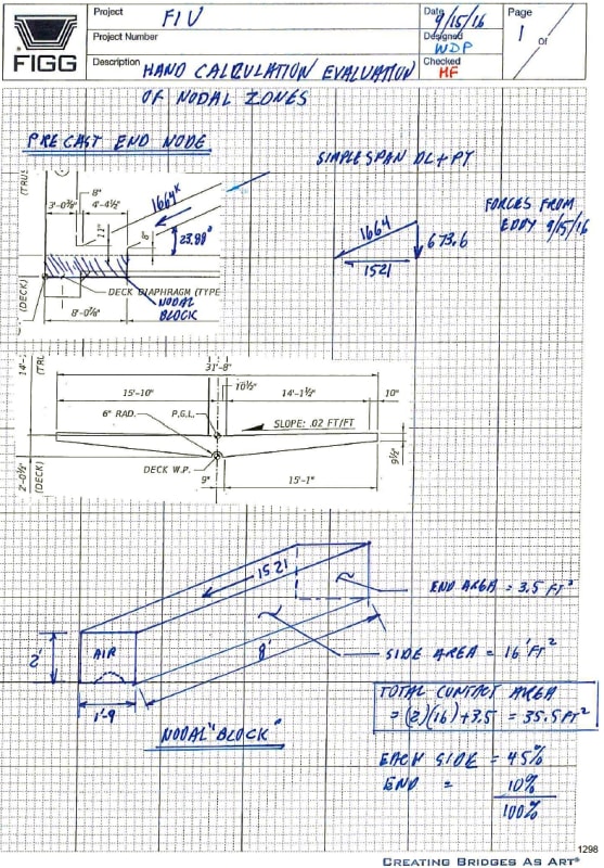
And thanks to jrs_87's post of links, here we have some nodal zone calculations for the beefier 1/2/deck connection.

This pdf doesn't include any calculations for the 11/12/deck connection.

[URL unfurl="true"]http://facilities.fiu.edu/projects/BT-904-PRR.htm[/url] > Calculations (zip).
> UCPP_Final_Calculations_Superstructure (1).pdf
PDF page number 1299 and following.

gw-calcs-1299_tvbnfi.jpg


... and a couple more pages.

And there are also pertinent calculations and design notes in document UCPP_Final_Calculations_Superstructure Misc Details.pdf
Section I Deck End Diaphragms.
"A strut and tie model was developed for the Type I and Type IV diaphragms to determine the steel area required for the tension tie at the bottom of the section between the two bearings. The tension tie, compressive strut, and node regions were designed per AASHTO LRFD 5.6.3.4, 5.6.3.3, and 5.6.3.5 respectively. Crack control reinforcement and shrinkage and temperature reinforcement were provided in accordance with AASHTO LRFD 5.6.3.6 and 5.10.8 respectively. The bearing replacement case was also checked, but found not to govern the design. Shear friction at the interface of the diaphragm and typical deck section was checked per AASHTO LRFD 5.8.4.1. A similar analysis was performed for the Type II diaphragm during casting (section supported by bearings) using construction loads. The results of this analysis were conservatively applied to the Type III diaphragm design. [...]"
 
gwideman said:
But the end of the deck is only adjacent to a tendon to its south, with obviously no tendons to its north. So, again naively, that last region of 4ft is covered primarily by "one side" of the last tendon, and no tendons to the north. So the force that the tendon would normally apply to 1ft 4in of midline is instead distributed to 4ft, resulting in only one third the compressive force per unit length.

Yes, but the tendons near the end of the bridge are acting over a smaller area of deck, thus the generated stresses increase. In other words, a tendon at the centerline of the diaphragm would, if it existed, generate twice the stress than one at midspan.
 
Status
Not open for further replies.

Part and Inventory Search

Sponsor