[Revised to add image of spreadsheet calcs, which correct a miscalculation in previous version. Basic conclusion remains the same].
OK structural people, could you take a look at this and tell us whether I've understood the following?
If I'm right, the crucial page of calculations that verifies sufficient strength of the strut-to-deck nodes seems to have some conspicuous problems.
3DDave said:
The other puzzle is that there are several areas where the number and spacing stirrups was done to keep the diagonals from rupturing, yet nothing about the amount of re-bar to take the shear loads at these locations.
I and others had been puzzled by not finding the calculations where the assessments of horizontal shear forces at 11/12/deck are compared to horizontal shear resistance provided across that plane by concrete friction and rebar.
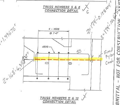
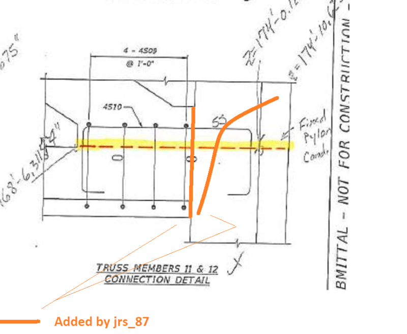
The relevant page appears to be: UCPP_Final_Calculations_Superstructure (1).pdf PDF Page 1284 (labeled 1283) where there are three tables listing and calculating several variables for each of the deck-to-member nodes.
It's a bit of a chore to understand all the variables, but they are described on pages PDF 1295 and following, though the example there is for vertical shear planes, and page 1284 is about horizontal shear planes.
(I also found a PDF 2012 copy of the AASHTO bridge manual which covers the same material, and is searchable for variable names:
Description of variables and reasoning:
bvi: width of interface (21")
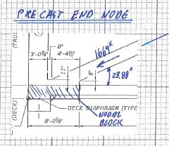
Lvi: Length of interface. For most of the nodes this matches the lengths shown on the drawings on PDF pages 1440 and 1441. Oddly, the lengths used for the end nodes are conspicuously shorter than the length on the drawings, but do correspond to the length over which the rebar is distributed, plus a modest amount. That oddity would underestimate the cohesion component of stress resistance, but that's zeroed out by c = 0.
Acv = bvi x Lvi Area of interface
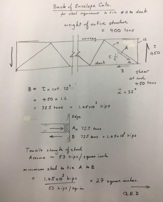
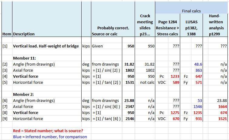
Pc: Compression force perpendicular to the shear interface. So in this case, the vertical component of Compression force in the diagonals. For the end diagonals 2 and 11, we would expect this to be half the bridge weight, or 950 kips.
For 2 and 11, Pc is overstated at around 1250 kips, which I will come back to.
VDC, VLL, VPT, VTU+TD. These are apparently components of horizontal stress. VDC (stress due to dead load of structural components and any nonstructural attachments) looks extremely understated for members 2 and 11. Given a vertical load of 950 kips, and member angles less than 45 degrees, the horizontal component
VDC has to be more than 950, not 589. And if Pc is supposedly around 1250, then VDC has to be more than that. (And in previous calcs I have shown it to be even higher.)
Vui: This is a crucial variable -- the total horizontal stress to be resisted.
Vui = the sum of VDC, VLL, VPT, VTU+TD multiplied by their respective load factors (provided in the "Load Factors" table.)
Needless to say,
if VDC is understated, then so is Vui, by an even larger amount since DC load factor is 1.25.
Avf: Area of rebars passing through the shear plane. Avf tells the number of rebars, which are all #7 whose cross section is 0.6 sq-in. These correspond to the bars seen on PDF page 1448.
None of the rebar area Avf figures look correct, and several of them are negative!
Since one of the purposes is to determine whether the rebars are sufficient, the fact negative rebar areas were not noticed seems to me a rather significant indication of the level of scrutiny this vitally important calculation underwent.
Lest we disbelieve that Avf is maybe not what I just described, continue on to the third table on the page.
Here the crucial variable is Vni, Nominal Interface Shear Resistance. One of the most crucial design checks is that shear resistance is greater than shear force, or Vni > Vui.
Vni = c x Acv + mu (Avf x fy + Pc) where
c (cohesion coefficient) = 0 for this analysis (making Acv moot, as previously noted)
mu = coefficient of friction = 1
Avf = area of rebar passing through the interface
fy = 60 ksi (shear resistance of rebar per area)
Pc = force normal to interface = 1233 for member 11. So note that
overstating Pc by 30% means the shear resistance will be overstated by 30%
So Vni = 1 (-2.28 X 60 + 1233) = 1096.
Note that this matches the third table, showing that the calculation blithely subtracted the shear resistance of the negative rebars, verifying that Avf is indeed what I surmised!
The negative rebars error understates the shear resistance, hence would have made the bridge safer, but it also shows that
effectively the shear resisting rebars were simply not calculated at all. So the calculations supposedly "validate" that all the shear resistance can come from the concrete friction resulting from the normal force, with no rebars.
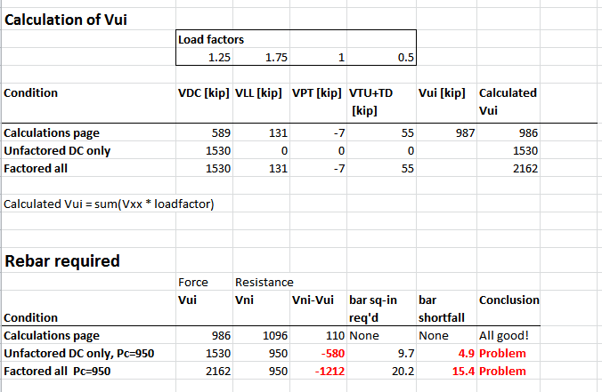
The following image shows several versions of the calculation of the shear force (Vui), and the implications when compared to Vni (shear resistance), and resulting rebar requirement.
Of note:
1. So far as I can tell, the bridge should have been designed according to the "factored all" row, in which case
the provided 4.8 sq-in of rebar is 15.4 sq-in short of the requirement.
2. But as a better idea of whether the bridge should be able to stand up at all, we might neglect the live load, and the load factor, and just use raw VDC as the horizontal shear.
That would result in a requirement for 9.7 sq-in of rebar, double what was provided. (The calculations page conservatively omits any reliance on concrete cohesion, so presumably there some additional shear resistance from that source not counted here.)
Summary:
[ul]
[li] The horizontal shear force VDC was stated as 589, clearly less than the 950 it would be for a 45 degree member (ie: no-calc reality check should fail), and hugely less than the 1531 I calculated for #11's actual angle of 32 degrees. [/li]
[li][/li]
[li] The horizontal shear resistance concrete friction component was overstated by 30% by overstating Pc. (But that error was reduced by the contribution of the "negative rebars".)[/li]
[li][/li]
[li] The rebar area was negative, which essentially means that so far as the calculations are concerned, the rebars were unnecessary for shear resistance, a clearly absurd result.[/li]
[/ul]
These problems appear so conspicuous that it seems hard to believe that these are the calculations actually used, or that these issues went unnoticed. Hence my interest in having someone with a structural background take a look.