EDIT: I re-uploaded the images but they still look like crap. A "feature" of the forum I guess....
Some notes on the SENSOR instrumentation, taken from the
Barnhart Movement Plan link provided by jrs_87 (Mechanical) 7 Jun 19 19:06
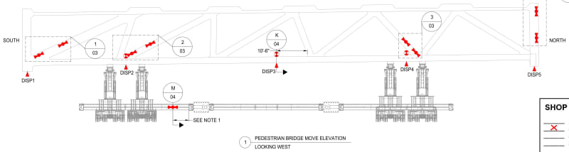
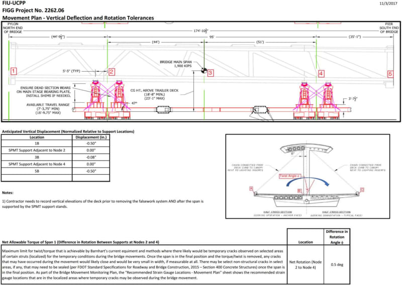
In the diagram below, columns 10 & 11 were not monitored at all, and rotation sensors were installed at the points marked DISP2, DISP3 and DISP4. These monitor the structure tilt in the lengthwise direction.
In the diagram below, at 5 equally spaced points (labeled 1-2-3-4-5, but the same as DISP1 to DISP5), 3 rotation sensors (labeled A-B-C) were installed at the deck edges and center. These sensors monitor the tilt of the structure across its width. NOTES:
[ul]
[li]The canopy chain is shown on the Twist Angle cross-section diagram as being connected to the deck curb, but as explained in my next section, BRIDGE TWIST is measured at points 2 and 4, where the canopy is chained to the SPMT arms.[/li]
[li]The comment box at the bottom describes how they expect the previously observed cracks to behave.[/li]
[/ul]
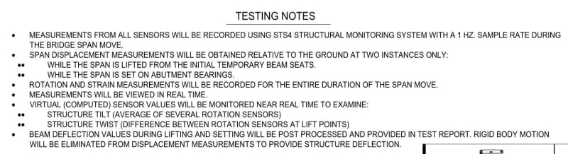
In the Testing Notes below:
[ul]
[li]STRUCTURE TILT is defined as the AVERAGE OF SEVERAL ROTATION SENSORS - I assume that will be DISP2-DISP3-DISP4 for the lengthwise tilt, and each set of A-B-C sensors at the cross section points 1-2-3-4-5 for the side-to-side tilt.[/li]
[li]BRIDGE TWIST is defined as the DIFFERENCE BETWEEN ROTATION SENSORS AT LIFT POINTS, which I assume are the A-B-C averages at cross section points 2 and 4.[/li]
[/ul]
My observations:
[ul]
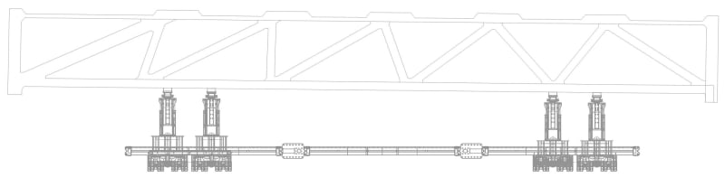
[li]Columns 10 and 11 are devoid of sensors. The sensor record will indicate "nothing happened" to them during the move.[/li]
[li]There are no sensors anywhere on the canopy, and BRIDGE TWIST is defined between two deck cross sections (EDIT: at "floor level") at points 2 and 4. The events I described in my earlier posts involve the canopy area at the 10-11 blister moving/flexing with respect to the deck, which is I assume remains rigid. The sensor record will also indicate "nothing happened" to this area.[/li]
[li]These two facts explain why the on-deck activity during the move "pause" did not seem to involve the area around columns 10-11.[/li]
[/ul]
It's been a long afternoon piecing this all together (and I'm hungry), but hopefully I didn't mis-interpretate anything from the Barnhart document.
One final note: Below is a drawing of the bridge as shown on the cover page of the Barnhart document. I can understand why it shows the exaggerated tilt, but why are the SPMTs not in the same location as they are shown in the sensor location image? They are shifted quite a bit to the north (right). Attention to details....