Navigation
Install the app
How to install the app on iOS
Follow along with the video below to see how to install our site as a web app on your home screen.
Note: This feature may not be available in some browsers.
More options
Style variation
-
Congratulations cowski on being selected by the Eng-Tips community for having the most helpful posts in the forums last week. Way to Go!
You are using an out of date browser. It may not display this or other websites correctly.
You should upgrade or use an alternative browser.
You should upgrade or use an alternative browser.
Miami Pedestrian Bridge, Part V 71
- Thread starter dik
- Start date
- Status
- Not open for further replies.
-
2
- #121
LittleInch
Petroleum
gwideman,
interesting looped video.
I'm pretty sure that as the collapse occurs you can actually see the bottom of member 11 and 12 bursting out of the end before they get dragged back into their final resting place. The top of member 12 has some bars sticking out and if you follow them down then you see it actually, for a short time sticks out the far side of the pier. Hence why there is debris from member 11 on the re-bar.
As I've said a few times, this collapse is so sudden and so brutal it is impossible to be 100% certain what is cause and what is effect. Maybe the bottom of 11/12 became detached from the base as part of the collapse, maybe it moved a bit and then became detached. I think as Hokie said in an earlier part of this post, we may never know, only establish a number of possible causes.
I'm not actually sure now where this post has left to go until new information is released by the NTSB. I think by now all reasonable theories and conjectures have been aired and we probably all have slightly different views on which is the most likely, but with so much missing critical information (e.g. reinforcement details, were they loosening or tightening the PT rod at the time of collapse, did the rod break or not, whether there were construction changes from the drawings, where was the crack, was there a cold joint, is there a block of concrete in the canal etc etc) I think we're in danger of just recycling and endlessly looping around.
Remember - More details = better answers
Also: If you get a response it's polite to respond to it.
gwideman,
Nice video concentrating on the failure mechanism. I find it very convincing.
I don't know about others but I would say the bridge failed because No.11 lost its restraint at the bottom. No.11 then became a moving mechanism (not a static component) carrying out of balance forces. Without No.11 the remainder of the bridge could not cope and bent at the bottom of No. 10&9.
I would disagree with the bridge failed first at the canopy joint at the top of No.11&10 because that would imply No.11 could still function as a strut then. The canopy section above No.11 has no structural duty except carrying the PT strands' anchors. The canopy in its final position will be in permanent compression. Therefore a complete removal of the end section of canopy on top of No. 11 plus a complete loss of the PT strands, which beneficially brings about a reduction of compression in the canopy, should not matter and theoretically cannot not cause the bridge to fail.
The reason why No. 11 lost its restraint (root cause of the collapse if the above is believed) and how the collapse was triggered are two different matters.
gwideman (Computer) said:This is Tomfh's animated GIF from 18 Mar 18 02:49 (Part I), but I've sped it up and looped it.
The faster frame rate and looping allows us to make better use of our visual system to see continuity of action.
(All are cautioned that this is still just 7 frames of fuzzy zoomed dashcam video, albeit with Tomfh's "dolly zoom" enhancement).
Half-size version below, full size version is in the attachments. (A bit overpowering to post in line, I thought.)
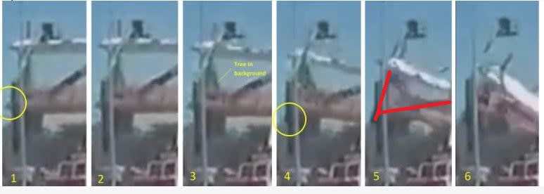
Would you loop the slow motion version that is posted on youtube? The slower speed helps to pick out additional details. It appears to show a white cloud of dust next to the worker and on the side of member #12.
Slow Motion Link
LittleInch said:did the rod break or not
I think we can conclude none of the rods broke because
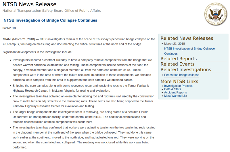
(1) NTSB news release last paragraph confirms south side all PT rod completed. North side one PT rod done and workmen were adjusting the second rod when the failure occurred.
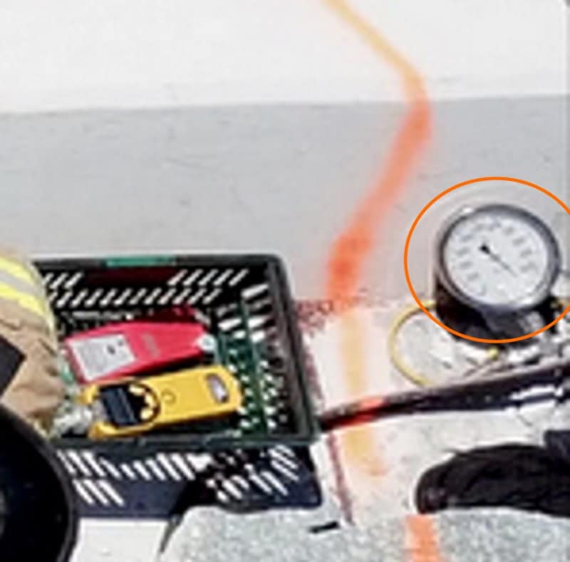
We now know the last rod worked on still had a jack attached after collapse and it was the bottom one of No.11.
(2) NTSB B-Roll video clip shows the bent threaded PT rod, how it rip out the concrete and broke the shear links in No. 11
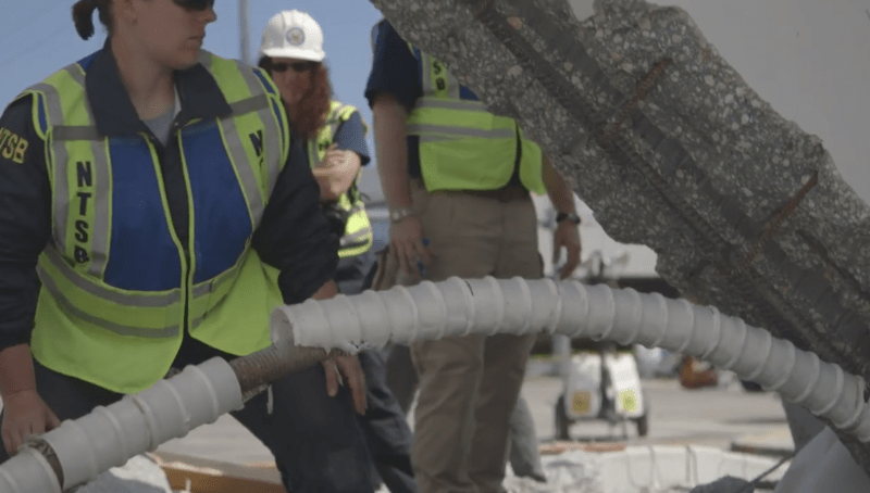
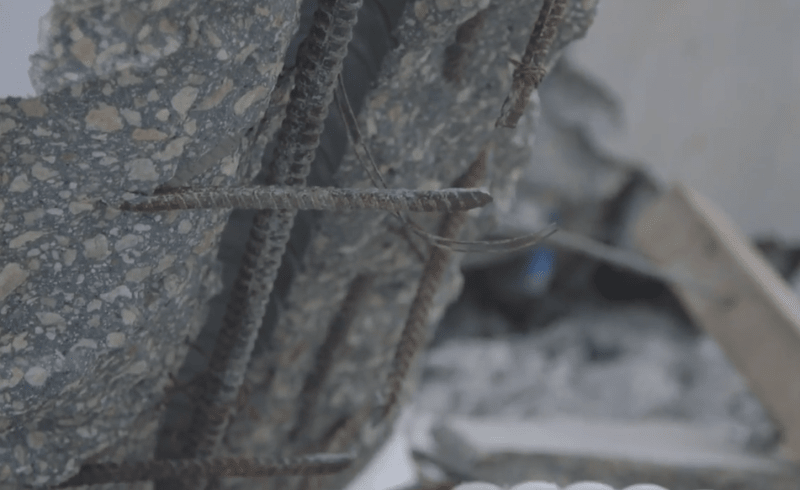
(3) If a PT rod broke that means concrete won and no crushing, No.11 has less axial load making it less likely to push out of its restraint and the bridge should still stand. If we insist may the PT rod had broken at a point hidden underneath the rubble now then the bridge failure had to be caused by the energy released by the breaking of one 1-3/4" PT rod. In that case we should expect to see the attached jack flying out from the bridge in some Youtube videos.
LittleInch
Petroleum
saikee119,
I agree with you that it seems highly likely that the rod did not break as otherwise why would it rip out of member 11? I just put it in the list because we don't know 100% for certain that it didn't and there has been a lot of discussion about if it broke or not. The NTSB report just says they were "adjusting" it. It doesn't say if it broke or not. We shouldn't start reading words which aren't there.
Equally the balance of probability is now that the rods were being tightened after apparently being released once the initial bridge installation was complete, but again, we don't know 100%.
Remember - More details = better answers
Also: If you get a response it's polite to respond to it.
-
3
- #126
LittleInch said:I'm not actually sure now where this post has left to go until new information is released by the NTSB. I think by now all reasonable theories and conjectures have been aired and we probably all have slightly different views on which is the most likely, but with so much missing critical information (e.g. reinforcement details, were they loosening or tightening the PT rod at the time of collapse, did the rod break or not, whether there were construction changes from the drawings, where was the crack, was there a cold joint, is there a block of concrete in the canal etc etc) I think we're in danger of just recycling and endlessly looping around.
Agree 100%
Check out Eng-Tips Forum's Policies here:
faq731-376
based on the video in gwideman's 20 Mar 18 7:00 post, which with the repeat is really nice (good job g) it looks to me like
[ol ]
[li]The mass that appears to shoot out the north end seems to be aligned with member #11, even to the point that is seems to be exiting from lower than the deck elevation almost along an axis if #11 was extended out the end of the section.[/li]
[li]It also looks like initially the base of member #12 kicks north (out the end) initially.[/li]
[li][/li][/ol]
My (uneducated structurally-wise) opinion of what it looks like to me:
The 11/12 joint sheared from the deck (as many seem to believe), possibly from relieving the PT which would reduce the clamp loading (shear resistance) of 11/12 to the deck. This initially punched out the north end moving the bottom of 12 with it. This is the "blob" that appears. Then as the entire structure collapses it pulls 11 and 12 from there position of being pushed off the north side but because they were still attached to the canopy they get drug south back over the top of the support. This is the point when "the blob" seem to be sucked back into the structure.
I contend that "the blob" may be the bottom of 11/12 as they sheared to the north and then got pulled back the other side as the canopy/11/10 collapse to the south.
LittleInch,
On your second point chris snyder on 27 Mar 18 04:09 posted a link to wusfnews. Tony Pipitone has reported like you said " the rods were being tightened after apparently being released once the initial bridge installation was complete". Pleople who have doubt should listen to the audio recording as from UK I know nothing about Tony Pipitone but he is a respected investigative reporter for NBC and his description of the event appear to be all factual as I cannot imagine he could say what he said unless being told by the relevant parties responsible regarding the previous transitional tensile stresses have been released before the road was open and then the chief engineer on return from the cracks meeting ordered some members to be re-stressed again.
In the discussions here we learn from each other and try to weed out information which is not factual. As a practicing engineer we learn from mistakes that is why people are interested even we have absolutely no influence on the actual investigation.
On your second point chris snyder on 27 Mar 18 04:09 posted a link to wusfnews. Tony Pipitone has reported like you said " the rods were being tightened after apparently being released once the initial bridge installation was complete". Pleople who have doubt should listen to the audio recording as from UK I know nothing about Tony Pipitone but he is a respected investigative reporter for NBC and his description of the event appear to be all factual as I cannot imagine he could say what he said unless being told by the relevant parties responsible regarding the previous transitional tensile stresses have been released before the road was open and then the chief engineer on return from the cracks meeting ordered some members to be re-stressed again.
chris snyder said:chris snyder (Electrical)
Been there a while, but just listened to this from Tony Pipitone.
Said they were tightening #11 when it failed, and that WORK was being done, not a 'stress test' (~3:30-4:40), among other things.
In the discussions here we learn from each other and try to weed out information which is not factual. As a practicing engineer we learn from mistakes that is why people are interested even we have absolutely no influence on the actual investigation.
saikee119 (Structural) said:I think we can conclude none of the rods broke because
(1) NTSB news release last paragraph confirms south side all PT rod completed. North side one PT rod done and workmen were adjusting the second rod when the failure occurred.
We now know the last rod worked on still had a jack attached after collapse and it was the bottom one of No.11.
(2) NTSB B-Roll video clip shows the bent threaded PT rod, how it rip out the concrete and broke the shear links in No. 11
Not so fast.
1) Don't believe the post-tensioning procedure has been seen. This should be documented as a work procedure.
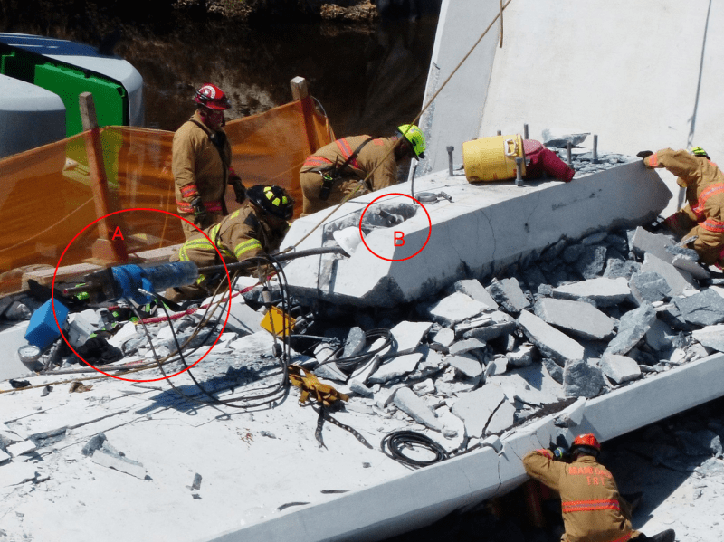
2) Does adjusting the post-tensioning procedure include chipping out space in the anchor blister for the hydraulic jack? Was the worker chipping concrete at the time of collapse?
3) Why does the post tensioning rod nut extend so far into the anchor blister?
4) What is the white dust that is seen around the worker shortly before the collapse?
5) Final as-built drawings have not been released and some parts of the structure are different.
It is all conjecture until what the post-tensioning crew were doing is documented.
-
1
- #131
bimr said:Would you loop the slow motion version that is posted on youtube?
That's an interesting request, however at the moment I don't have a method for grabbing video from YouTube. I know there are programs and web sites that claim to do that, but last time I looked they all seemed very shady, wanted you to install potential virus-infested software, or sign up for spam. (But I'm open to suggestions from anyone with a non-shady method.)
That said, a couple of notes:
[ul]
[li]Your link points to: [URL unfurl="true"]https://www.youtube.com/watch?v=D6pGzgm4zZ4[/url], a channel belonging to Zac Doyle. It is a slow-motion video with impressively smooth motion, implying a lot of distinct frames of video.[/li]
[li]That video's notes point to Zac's interesting blog post at: [URL unfurl="true"]http://zldoyle.blogspot.com/2018/03/photogrammetry-of-fiu-bridge-collapse.html[/url][/li]
[li]That post in turn points to Zac's original source for his video, a YT channel named OfficialJoelF: [URL unfurl="true"]https://www.youtube.com/watch?v=Ucflj-MsJBI[/url]. This is almost certainly not the original, and is a fast-motion video, though the notes say "I decided to slow down the dash cam and zoom in". [/li]
[li]A commenter on Zac's post pointed to this video [URL unfurl="true"]https://www.youtube.com/watch?v=jzbfJF5iVpI[/url], which provides a longer span of time and a larger frame view, and is even faster-motion. (Fast motion really just corresponds to the dash cam frame rate being far slower than 60/sec, which is a reasonable way to economize on data storage for dash cam purposes.) But that link has only a few views, so seems unlikely as the original upstream source.[/li]
[/ul]
Anyhow, Zac managed to produce a video running at some slow-motion rate that nonetheless has very smooth motion, supposedly based on a fast motion video with very obviously not-smooth motion. There's something significant missing from this story.
Either Zac has access to a video that has a lot more frames per second (and mistakenly linked to the wrong source), or he has interpolated the sparse-frame-rate video to produce intermediate frames. Zac's article talks about interpolation, but I initially assumed that was with regard to interpolating identifiable points in the image. I don't know much about interpolation of video frames, but presumably that can be done using a morphing technique, given enough identifiable points from frame-to-frame of the original video.
Bottom lines:
1. It would be useful to know where the original original dash cam video is, or came from, and work with that raw data as a starting point.
2. We should be cautious of enhancements, as any enhancement "adds clarity" by imposing its model of what happened. For example, an enhancement might use linear interpolation of motion between frames to generate new frames. In any case, we should at least be aware of what enhancements have been performed.
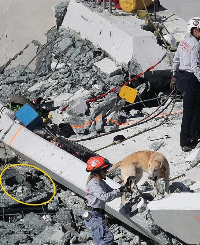
Photos of the concrete blister on top of the truss canopy where the tensioning operation was taking place at the time of the collapse indicate that concrete chipping was necceasry. The surface around the anchorages is rough and uneven and there is a chipping hammer shown in bimr’s last post.
But photos of this same area during the roll in show the same uneven rough surface around these anchorages. Why is that? Was there some uncertainty surrounding these anchorages before the roll in that required their anchorages to be exposed? Why would access have been a problem if the plan had all along been to de-tension the bars after the girder was placed? If that was the case why not properly form a ressess for the future work?
I agree, more info is needed in order to go further.
TheGreenLama
Structural
Gwideman, as your two recent posts show regarding the Tomfh video, it's clear that the bulge you noticed is the base of 12. However, it's impossible to say what the 11-12 connection status is.

TheGreenLama
Structural
Gwideman, any chance of removing the construction worker on the top deck from the video out of respect?
Retiredat46
Member
Do these two photos show a crack around three sides of the bottom of #12, or is that just an illusion?
From an earlier post about the pvc pipes:
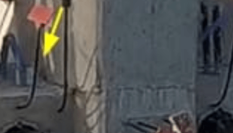
From the end of the video taken by the camera on the end of the bridge during the move:
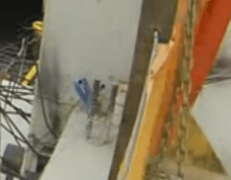
From an earlier post about the pvc pipes:

From the end of the video taken by the camera on the end of the bridge during the move:

-
1
- #137
bimr (Civil/Environmental) 28 Mar 18 16:04
[...] 2) Does adjusting the post-tensioning procedure include chipping out space in the anchor blister for the hydraulic jack? Was the worker chipping concrete at the time of collapse?
If the de-tensioning had previously been completed and they were re-tensioning, why would they need to chip out space?
In gwideman's post of 28 Mar 18 07:00 with the looped video it appears that the crane is backing up during the sequence; not sure if this is due to zooming but the car is moving forward.
Also to sailkee119 I thank you for the information on the deck and canopy tendons. Appears then that the 6-12 tendons were swapped from outboard to inboard in the deck if we look at giideman's post of 27 Mar 18 15:04. Less pre-tension in the critical centre area of the suspect failure zone.
Also to sailkee119 I thank you for the information on the deck and canopy tendons. Appears then that the 6-12 tendons were swapped from outboard to inboard in the deck if we look at giideman's post of 27 Mar 18 15:04. Less pre-tension in the critical centre area of the suspect failure zone.
LittleInch
Petroleum
kbp69,
Pure speculation, but maybe as per the original design, as these tendons were supposedly only there for the lifting process when members 2 and 11 were in tension, were then de-tensioned not long after the bridge was put on the piers and hence their job was done so they were then grouted in to smooth off the top bullets and avoid any water getting into the tendon tubes?
If so then it shows that this probable re-tensioning was not a planned occurrence but a reaction to this mysterious crack.
Remember - More details = better answers
Also: If you get a response it's polite to respond to it.
- Status
- Not open for further replies.
Similar threads
- Question
- Replies
- 27
- Views
- 24K
- Replies
- 1
- Views
- 4K
- Replies
- 13
- Views
- 13K
- Replies
- 6
- Views
- 3K
- Replies
- 17
- Views
- 11K

