Continue to Site

Eng-Tips is the largest engineering community on the Internet

Intelligent Work Forums for Engineering Professionals

  • Congratulations GregLocock on being selected by the Eng-Tips community for having the most helpful posts in the forums last week. Way to Go!

Miami Pedestrian Bridge, Part V 71

Status
Not open for further replies.

dik

Structural
Apr 13, 2001
25,816
This continues the discussion from Part I, II, III, and IV. Please read the other threads first:

Part I
thread815-436595
Part II
thread815-436699
Part III
thread815-436802
Part IV
thread815-436924
 
Replies continue below

Recommended for you

bimr said:
3) Why does the post tensioning rod nut extend so far into the anchor blister?
The rod must be long enough to accommodate the nut, when in the untensioned state.
Additionally there must be enough added length to attach the tensioning jack.
There may have been a little extra length as a safety factor.
Hence the extra length of the rod protruding out past the nut.
Although the rod in member 11 was not permanent, normally the cavity in the blister must be deep enough
that the protrusion of the rod may be completely covered with concrete or grout when the final tension was set.


Bill
--------------------
"Why not the best?"
Jimmy Carter
 
saikee said:
I don't know about others but I would say the bridge failed because No.11 lost its restraint at the bottom

Member #11 was buckling as soon as collapse began, and fell straight downwards. If #11 slipped off I'd expect it would keep going?

bmir said:
Would you loop the slow motion version that is posted on youtube? The slower speed helps to pick out additional details. It appears to show a white cloud of dust next to the worker and on the side of member #12.

This is an impressive video, but be careful of using it to study the details. Most of the frames are fictional.
 
waross said:
The rod must be long enough to accommodate the nut, when in the untensioned state.
Additionally there must be enough added length to attach the tensioning jack.

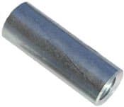
The extension of the PT bar beyond the nut must accommodate AT LEAST half the length of a mechanical threaded coupler (see photo below, which are 8-1/2" long for a 1-3/4" PT bar). A short, temporary "pull bar" is most often used, and it connects the stressing jack to the PT bar assembly. A stressing stool (usually a custom-made heavy-walled tube with a annular bearing plate, and a reinforced side-wall cutout) is used that bears on the tendon bearing plate, and enables the pull bar, nut, washer, and coupler to freely elongate, and also enables the stressor to then adjust the nut.

150_ksi_coupling_qyjpwg.jpg
 
First time poster - retired - MSEE but never took the PE.

I'm posting this to provide some background on the original dashcam video, and hopefully explain some of the misunderstandings about the many versions of it that are floating around. (Provided I insert the links correctly!)

The earliest known post of the dashcam video was made by Twitter user @o2webdev. If you search for that name you'll find that his real name is Oscar Fuentes, and he has since deleted almost all his media accounts after his twitter name was mentioned in several web articles. He seems to be a software guy rather than a truck driver, so he may not be the original, original poster.

There are several blurry, low-rez duplicates of his video floating around, but only a few versions exist that appear to be "high-quality" direct copies. One of these copies was previously noted by gwideman 28 Mar 18 16:21 - [URL unfurl="true"]https://youtu.be/jzbfJF5iVpI[/url] - but the poster doesn't know who shot the original video. It was also uploaded on the 18th.

The earliest known HQ copy I could find was a shortened version posted March 16th, on the Twitter account of Joel Franco - [URL unfurl="true"]https://twitter.com/OfficialJoelF/status/974834499140898817[/url] - He properly identifies his source as @o2webdev.

Franco also posted a "slower" version of the original that "zooms in" for the second half. I've seen some confusing comments about similar videos, so here is a simplified explanation of what is going on to create a slower, zoomed-in video:

The dashcam video was shot at five frames per second (5fps), or one frame every 200ms. When played back at the PC standard of 30fps, this causes the video to run at a speed that is 6 times faster than normal. To create the illusion of a slower, smoother video, Franco used an 2-D interpolation routine to calculate in-between frames. Simple averaging can't be used because each pixel moves to a different X-Y location in a following frame.

Other videos that look like they're running at "normal" speed, but have a dream-like quality, were created by interpolating up to 5 (FIVE!) intermediate frames between each pair of original frames.

Other editing schemes create the illusion of a slower video by inserting duplicate copies of each frame. This results in a jerky motion, like old 1920's motion pictures. Padding an already interpolated video with duplicate frames slows the playback speed by at least a factor of four: frm1-dup-int12-dup-frm2, etc.

The second half of Franco's interpolated video is also zoomed. The original video was recorded at a standard 1280x720 pixels (aka 720P), so a simple 2X zoom means that a central area of 640x360 is "enlarged" to 1280x720 by creating "in-between" pixels that are a weighted average of the immediately surrounding pixels. Please note that a 2X magnification requires a 4X increase in the number of total pixels, not 2X!

Also, hybrid videos that are interpolated first, then zoomed, may have significantly different calculation artifacts than ones that were zoomed first, then interpolated!

And finally, there are a few videos that use a pan-and-scan technique that dynamically adjusts the zoom so the apparent size of the bridge remains constant, even as the camera grows closer. This results in the mindbending illusion of stationary vehicles magically moving backwards, and objects in the bridge foreground/background moving sideways. This is the dolly-zoom effect made famous by Alfred Hitchcock in the staircase scene of Vertigo.

In summary, much of what you see in these slowed down, zoomed in videos is artificial, the result of frame-to-frame interpolation and multi-pixel averaging. Better looking is not the same as more accurate....
 
Thanks guys for the better videos

the clarity of this one linked by Gwideman and MikeW7 is a comfort to me. Looks as if it's close to the source. Even shows the reflection of his coffee mug in the windshield...

Even shows the "Mystery Projectile" .
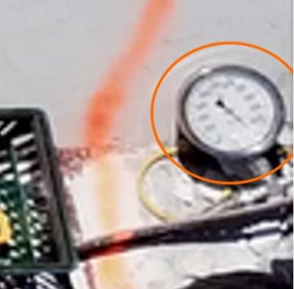
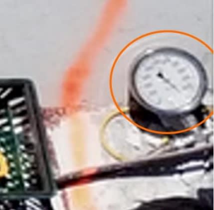
In light of Epoxybot's image of the overranged pressure gage

fiubridge32_mayxdi.jpg


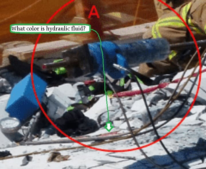
i'll speculate "Mystery Projectile" is a spray of hydraulic fluid.
A really strong tug on the tensioner rod from its other end would pressurize the fluid in the jack, P = F/A after all.
I believe the lower #11 tendon was anchored in #12's bottom.
As #12's bottom pivoted out to North it'd initially yank mighty hard on that tensioner.
Resulting hydraulic pressure may have blown a hose ftting or lifted a relief valve spraying oil.
A snip from bimr's picture at 16:04 above
fiubridge33_ff1lpu.jpg


Speculation of course.... i'd initially feared the worst (blood) but this seems more logical in light of that clearer video and the overranged gage...

thanks again

old jim


Never trust a computer with anything important...
 
Bimr,

I trying my best to answer your 5 questions. I am UK qualified but most my work has been overseas using principally American, British and European codes. I have a general idea about the design and build contracts and have worked on project pouring 1000m3/day for months.

(1) It is customary for the D&B consortium, in this case MCM+FIGG, to submit a method statement before the bridge is constructed. A section of the method statement will has to cover post-tensioning the multi strands (between 7 to 19 no. of 0.6" tendon) and PT threaded single bar (1-3/4" dia). That information is submitted to FIU the client and his Inspection/supervision unit. This post-tensioning procedure could be just standard guideline handed out by the PT strands and bar manufacturers detailing how to measure elongations to monitor the stress and making use of their equipment. It is unlikely provide to the public. There is no ground for us to suspect any unsafe practice because the procedure is a good engineering practice produced and refined after hundred and thousands of applications. The special bits if any would be the sequence of application particular to this bridge. FIU inspection authority is unlikely to permit the work to go ahead until all these documentations are submitted as a proper procedure will have sample record sheets to be signed by all parties.

(2) I don't have facts on this one but chipping out obstructing concrete to access the PT rods and nuts. Such work would need permission from the consortium engineer team. The NBC investigative reporter Tony Pipitone said the initial tension adjustment had been executed before the road was re-opened. The contractor might have sealed the pockets with mortar, temporary or permanently, to protect the steel from rusting. Once the tension adjustment has been completed the consortium has no reason to reopen the access pockets.

(3) old jim (Nuclear) on 26 Mar 18 05:06 and chris snyder (Electrical) on 27 Mar 18 22:35 have explained to us that No.11 is now resting at a steep angle but the bottom PT bar is on the ground with one exposed bend and possible other bends buried under the bridge. Since the diagonal is longer than its horizontal projection so they believe the No. 11 extended bottom PT bar, still with a jack attached on the blister, was pushed out during the fall.

(4) I have no data to confirm the white dust in the video. When Tony Pipitone was asked the same question he said he didn't know as it could be materials from the construction like, concrete, grout, steel etc. Personally I attach little significance to imprecise and manipulated video recording except for corroborating other evidence.

(5) As-built drawings will never be available for this bridge because it has collapsed. If the same bridge is to be rebuilt it will have numerous modifications no longer comparable to the current design. For the collapsed bridge there should be a set of execution drawings, possibly prepared by MCM or MCM's consultant who could be Figg himself by suitable financial arrangement, for the construction work. It is unlikely to be made public. The way I see it is that Figg has sold the design by wining the bid. Their obligation is to turn the proposal drawings into a set of design drawings completed with calculations. Structural requirements like steel reinforcement will be provided. MCM has to construct it by adding the missing details. I think the American system is the designer just specified say 10#7 bar at 10" centers of reinforcement on the design drawing and the contractor has to work out the lap lengths, bend dimensions, add trimmer bars if required, chairs to support the steel and prepare the bar bending schedules. We can be opening a can of worms here.

 
MikeW7 said:
I'm posting this to provide some background on the original dashcam video
Thank you MikeW7 for that very informative post. An understanding of the nature of the evidence at hand is essential to understanding what it tells us about the events it depicts.
 
Following up on bimr's earlier request (28 Mar 18 10:59) to analyze [URL unfurl="true"]https://www.youtube.com/watch?v=D6pGzgm4zZ4[/url] good-looking smooth slo-mo video, and my response (28 Mar 18 16:21) regarding cautions in doing so.

Zac Doyle has responded ([URL unfurl="true"]https://zldoyle.blogspot.com/2018/03/photogrammetry-of-fiu-bridge-collapse.html?showComment=1522264984736#c117024334901533913[/url]) to my question about video interpolation, (and his answer fits nicely with MikeW7's):

From the video source I used, which I linked above, I interpolated the entire frame area. You can see this from the artifacting at the edge of the frame as objects fall off. Originally, the dashcam captured 17 frames of video during this segment of the collapse. The process I used interpolated it out to more than 2000. And yes, the process would be highly similar to morphing images. Around 500 reference points are placed in each frame and from that the motion is interpolated stretching each frame for approximately 2 seconds.
 
I can't imagine a loading condition for this bridge that would have required the asymmetry of the trussing. Doesn't make sense to me. Anyone have an explanation?
 
Ron - to match the angles of the fake cable stays and semi-symmetry with the other half that wasn't in place yet.
 
TheGreenLama:

Responding to your request at (28 Mar 18 17:04) to mask out portions of the video, and acknowledging the solemnity of your request. I did consider that before posting, but felt that for this engineering forum the merit of preserving the data outweighed other factors. This is, after all, just a copy of data that has been published unmasked hundreds or thousands of times before, including on this forum, which was my source for the data. The one or more clusters of blurry pixels are so indistinct that they may or may not be personnel, and if they are, their position may offer important information. I recognize that others might weigh these factors differently though.
 
3DDave....yep....I had forgotten that this bridge was more architectural than structural!
 
The NTSB will not assign blame as it is not their job; neither I believe is it the objective of this forum to assign blame but to try and uncover facts. We are trying do this with a lot of questions that may never be fully answered simply because some of the evidence may never be revealed to the general public. During an actual trial(s) that could go on for years they could be demanded by one or both sides. The NTSB also may have power to subpoena documents but may not disclose what is in them.

If whatever we don't know is not relevant to when, what, and why we will probably never know. If f'c in various parts is not relevant we may never know where what f'c was used and so on.

 
chris snyder said:

I like the computer modelling approach.

UKJim said:
My estimate for the load on 11 is smaller (see my previous post above). Based on the member sizes in the conceptual design, I calculated a reaction at the north pier of 910 kips (slightly less than the 950 kips in the press accounts).

A portion of this total reaction is the dead weight of half the last span of the base slab and half the last span of the canopy slab. Those forces are not carried by 11.

In addition, the weight of 12 is not carried by 11.

Making those adjustments reduces the unfactored dead load force in 11 to around 1150 kips, plus PT.

With the help of the same online truss calculator, I modelled the truss of the pedestrian bridge and calculated how 50% of the weight of the bridge (about 950 kips) would be added to the bottom end joint of the truss and onto the north pier by
[ul]
[li]the end span of the deck (130 kips - 6.8%),[/li]
[li]truss member #11 (777 kips - 40.9%) and[/li]
[li]truss member #12 (43 kips - 2.3%).[/li]
[/ul]
South ---------------------------------------------------------------------------------------------------------------North
Full-size image file uploaded to ENGINEERING.COM.[/url]

Model parameters
I assumed that the canopy and truss members were 1/3 of the weight of the bridge and the deck represented 2/3 of the weight.
I modelled the canopy and truss members as a distributed load of 3.683 kips/foot.
I modelled the deck as a distributed load of 7.373 kips/foot.

Results
The end span of the deck adds half of the span's weight to the end joint - 130 kips, 6.8% of the weight of the bridge.

Member #11 adds 777 kips, 40.9% of the weight of the bridge, which equals an axial compression force of 1367 kips multiplied by the sine of the angle of member #11 to the horizontal.

The end column, member #12 adds 43 kips, 2.3% of the weight of the bridge, which equals half the weight of the end span of the canopy and the weight of member #12.

Conclusion
The axial compressive force of member #11 at only 1367 kips is notably less than had been calculated earlier when approximating that the deck only provided a tension force to the end joint and neglecting the real effect of the weight of the end spans of the canopy, the deck and member #12.
 
been following this, esp about video
1) there does seem to be a projectile. I thought maybe a small chunk of concrete broke loose when rods popped out a bit at first shift (assuming the cold joint at base of 11/12 moved as shown in gwideman's diagram, IV-23 Mar 18 17:09). The jack's contact surface would need to be cleared, but not the corners of the bearing plates.
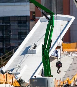
2) I can't find good photos (wanted to compare how much thread was exposed), but the 2-3 blister was also chiseled open. And not sure how much, but chiseling up top would send impulses to lower end - not good if 11-12 to deck was cracked.
05-south_end_blister_ylodfs.jpg

3) there may or not be dust, but chiseling would be done before the jack was placed - else the jack would be in the way.
4) maybe others know, but I think I see another worker up there barely visible to left of crane (maybe he stands just before collapse??). Article said a worker latched his harness a 'few seconds' before collapse when he heard a crack and credits this with saving his life (in reality, this could have been less than a second). I get a sinking feeling seeing Navaro Brown (R.I.P.) fall with that harness dangling, and harnesses laying on top of the blister.
5) gwideman's loop makes some things apparent. Like the 11-12-canopy triangle holding together. On frame 6, (to me) it appears the 11-12 connection which has moved north (sheared together, covered with black banner) grays up and gets blurry like it's beginning to 'explode' - this point moves off screen after this happens (some videos don't even show it).

I suspect the 11-12 joint 'exploded' when it was over the pier - as the canopy came down and "chopped" a few feet off the top of #11 because the canopy broke at the north edge of blister (seen in video). It would take a tremendous amount of energy to pulverize that much rebarred concrete and that joint compressing (like squeezing a wishbone) might do it.

Tony Pipitone seemed definite about the rods being tightened, AND (angry) when he said "stress test" was a "misnomer" (a tactful way of saying it was a blatant lie). There was no reason to tighten rods on compressive members (now I know why you all wondered if they were de-tensioned). Mr. Pipitone also said ~"WORK was being done to address what was discussed at the meeting" which I take to mean the cracks, but he didn't say that (though I sense he knows), and is angry about them doing such work with people/cars below. Marco Rubio's tweet (first info to come out) also said they were tightening the rods.
 
Chris - the blister openings were like that before the bridge was transported. The tensioning of all the members would have to happen before lifting the bridge. The "harness" was likely the sling used to lift the hydraulic jack into position.
 
Toomas Kaljas updated his dropbox post. It appears he has the width of trusses as 24" (vs 21" in preliminary Sept 2015 spec pg 115), but relative forces would be the same. For some reason there's a big difference in stress on member #12 than #1.

This blows me away and I'll have to study it - and Peter Dow's post above.
Such analysis is way beyond my electronics background - I appreciate learning from everyone.
 
3D Dave said:
Chris - the blister openings were like that before the bridge was transported. The tensioning of all the members would have to happen before lifting the bridge.
Ah yes - I see now looking at overhead when span was being moved. There was question if these were filled when placed - supposedly tensioning [which could be detensioning] was completed the day it was moved, then [tensioning] re-done after cracks appeared. Saikee119 said unsealing blisters would be a big deal and require discussion, etc. Question first arose from seeing small jackhammer in rubble.
 
Ingenuity
Thank you for the picture and explanation of the threaded coupler and further explanation of my post.
On another topic:
I have been wondering about the picture of the pressure gauge.
The needle on many gauges is a press fit on the shaft. I have seen some pointers moved by pressure pulsations or by a sudden application or release of pressure.
Rather than jump on this picture as evidence of over pressure, I am more comfortable with the theory that the needle has shifted due to abrupt pressure changes during the collapse.
The background to the photo and the red line apparently spray painted past the gauge may support this theory that the picture was taken post collapse.
Comments?

fiubridge32_mayxdi_aztets.jpg


Bill
--------------------
"Why not the best?"
Jimmy Carter
 
Chris - anything is possible. I do note that the tensions on both #2 and #11 would need adjustment after the move, but only #11 is associated with further concerns, so if they had filled the openings after the post-move adjustment, why would they also open #2, which was intended to be tensioned in the original plan versus #11 which was not to have any tensioning at all.

This makes the jack hammer a puzzle, but the photo is after the start of rescue and recovery efforts, so I don't know if it was in use on the top of the bridge.
 
Status
Not open for further replies.

Part and Inventory Search

Sponsor