Eng-Tips is the largest engineering community on the Internet

Intelligent Work Forums for Engineering Professionals

  • Congratulations waross on being selected by the Tek-Tips community for having the most helpful posts in the forums last week. Way to Go!

Miami Pedestrian Bridge, Part V 71

Status
Not open for further replies.

dik

Structural
Apr 13, 2001
25,564
0
36
CA
This continues the discussion from Part I, II, III, and IV. Please read the other threads first:

Part I
thread815-436595
Part II
thread815-436699
Part III
thread815-436802
Part IV
thread815-436924
 
Replies continue below

Recommended for you

Interesting turn of events - based on these video comments, the dashcam was in a semi that was leaving the MCM construction area where the bridge span was built. This could put the owner/driver/uploader/(all of the above) in serious legal trouble. No wonder @o2webdev tried to erase his web footprint.
 
If we are going to run computer models lets at least get the loads/ft correct, so in the spirit of joint effort why not use calculated numbers. Biggest room for error here is scaling the length of web members

Taking the area of the canopy it is 16.29 ft2 so at 150 lb/ft3 this is 2.44 k/ft. or 427 k. The deck area is 48.01 ft2 so with the same density it is 7.2 k/ft. so total deck wt for 175 feet = 1260.2 k. Accumulated total 1687.7 k.

I estimated the web to be a total of 200 feet of 1.83 x 2.0 x 0.15 = 109.8 K plus the two end verticals 30 ft x 1.83 x 2.83 x 0.15 = 23.3 k for a total of 133.1 accumulated wt now 1820 k. Blisters on deck Total of 5 x 7' x 3.5 x 1.58 x 0.15 = 29.0 k for a total all in weight of 1850 k. Overall reaction = 925 k. Deducting 1/2 of canopy from top of 11 to 12 = 0.5 x 30 x 2.44 k/' = 36 k minus member 12 = 29/2 = 18.5 for total deduction of 54 k. I did not deduct a portion of deck here because it is required to make an effective truss.

Calculated reaction is = 925 - 54 = 871 k

If the angle is 36 degrees which seems to be consensus then axial load in 11 = 871/sine(36 deg)= 1481 K as opposed to 1367 as calculated by 1367 k used in the model above. These numbers included an allowance for concrete of 145 lb/ft3 allowance for steel of 5 lb/ft3 or 135 lb/yd3. This is an average reinforced area of about 1% of concrete area which would be = 0.01 x 144 x 3.4 = 4.9 lb/ft3.

5 lb/ft3 allows for about 5 x 1850/(0.15 x 2000) = 30.8 tons Probably a bit light here but about 2.5 X what minimum reinforcing would be for shrinkage and temperature. If I am low here let me know. In a 22" by 24" web member it would allow for about 1.83 x 2 x 0.01 x 144 = 5.27 in2 of steel, 10-#7 bars would be 6.0 in2 so for the web I am a bit light perhaps because we require stirrups to keep rebar in place. Deck strands alone say 10- 6-19 and 2 - 6 - 12 would be 41.2 in2 + 5.2 in2 = 46.4 in2 vs my total allowance of 48 x 0.01 x 144 = 69.12 in2 so that leaves about 23 in2 for standard rebar or 23/69 x 0.01 = 0.0033%. should be close if not ok. Canopy same.

So the above neglects the wearing course recommended in the call for proposals, voids for electrical, electronic and other conduit, non grouted ducts, deck drains. I also did not include the weight of the two concrete curbs added to the deck, both might add another 75 to 100 lb/ft. to the actual load.

Anyway my 2 cents, just hope that I have not made any major errors or omissions not noted, just remember I'm experienced (old) and retired. If someone has the geometry fairly accurately I would be happy to run this on my software here at home. Have to fire up my old Mac to do it but should do it anyway. If I get any feedback and some half arsed geometry will have a go at it.

 
If this were just a truss, you wouldn't need help from a computer, because this truss is totally determinate for axial forces. Fine for a steel truss. But this is not just a truss, it is a concrete frame.

appster, I think the result of the investigation will assign blame clearly enough.
 
hokie66 "appster, I think the result of the investigation will assign blame clearly enough." Actually they very seldom point out one cause or name anyone specifically because usually a number of things add up to why it happened and they usually make recommendations to prevent the same thing from happening again. Blame will be assigned mainly by those reading between the lines of the report. Hey if I am wrong it won't be the first time but I have never had a structure fall down or fail to perform as intended.

Many will try and assign blame to as many as possible through the courts.
 
waross - There is also the possibility that the pump was running when the collapse took place and simply maxed out after the collapse. I can;t say, Ingenuity is the best source.

On another note, Philadelphia Construction Engineering on his youtube channel points out that only 4 of the six PT strands were tensioned in the canopy making the canopy "soft" around the blisters. Link

4_xowacy.jpg


While not extensive there is spalling on the top-inside face of the pylon.

3_b5fupr.jpg
 
appster said:
Actually they very seldom point out one cause or name anyone specifically because usually a number of things add up to why it happened and they usually make recommendations to prevent the same thing from happening again. Blame will be assigned mainly by those reading between the lines of the report.

Very much this. Most accidents (or even more broadly 'events') have multiple causes. There might be one prominent 'trigger' but deeper analysis normally reveals multiple mistakes in the pathway that lead to the ultimate trigger point.
 
saikee119 (Structural) 29 Mar 18 00:20
[...] (2) I don't have facts on this one but chipping out obstructing concrete to access the PT rods and nuts. Such work would need permission from the consortium engineer team. The NBC investigative reporter Tony Pipitone said the initial tension adjustment had been executed before the road was re-opened. The contractor might have sealed the pockets with mortar, temporary or permanently, to protect the steel from rusting. Once the tension adjustment has been completed the consortium has no reason to reopen the access pockets.

chris snyder (Electrical)29 Mar 18 02:27
2) I can't find good photos (wanted to compare how much thread was exposed), but the 2-3 blister was also chiseled open. And not sure how much, but chiseling up top would send impulses to lower end - not good if 11-12 to deck was cracked.
05-south_end_blister_ylodfs.jpg


It appears the lower blister is grouted.

If only we had minutes from the morning meeting!
 
In regard to the NTSB investigation and what to expect, I refer to the investigation into the I35W bridge collapse in Minnesota in 2007. The report was issued about 16 months after the collapse. The report was unequivocal in assignment of probable cause and blame. Design error in design of some of the gusset plates.
 
epoxybot,

You might have something there. All the original concept drawings show 6 tendons in the top canopy. Your picture from the South end shows only 4, but with the inner holes there, but not filled.

The Northern end though looks a completely different end design, maybe because it was going to be filled in or connected to the canopy on the second span. There is certainly a lot of spare re-bar sticking out see below. The longer grey tubes look like they might be drain pipes, but clearly different from the tendons. The fact that the South end clearly has the holes made and ready for the tendons and North side doesn't implies something changed during construction.

So maybe the initial failure was at the top of 11/10 and not the bottom of 11/12. It's always been 50/50 in my mind. With a worker on top apparently reporting hearing a "cracking noise" just before he locked in his harness ( whatever that means) and seconds before the collapse might imply some failure closer to the canopy section than the floor.

stess_points1_qh9bbm_rvlgac.jpg

Stress_points_cgmqdt_dllmnw.jpg


Remember - More details = better answers
Also: If you get a response it's polite to respond to it.
 
@appster - your numbers are about what I calculated (I also scaled the drawings). I don't have my numbers in front of me; left them at the office. Anyway +/_ 5 or 10% isn't going to matter. Without a full set of plans, calculations, etc, it's all speculation.

I agree with LittleInch; this thread is just going around in circles now.
 
Still photos of the Bridge Deck (Completed Rendering).
render3_jdwexs.jpg


Still photos of the Central support tower (Completed Rendering).
pylon_zxaoph.jpg


The photo on the bottom here looks like the concept design might have been a true cable stay bridge, I have a feeling the replacement bridge will lean towards it.
TYLIN_UniversityCity_1_980x487_qmj8x2.jpg
 
They obviously aren't photos of the bridge (completed). I don't know why you think those pictures suggest that the bridge was to be cable stayed, any more than what we already know.
 
LittleInch (Petroleum)29 Mar 18 09:13 & epoxybot (Structural)29 Mar 18 05:33

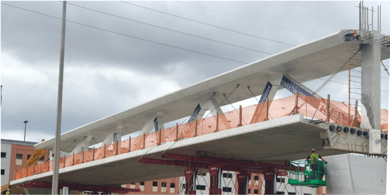
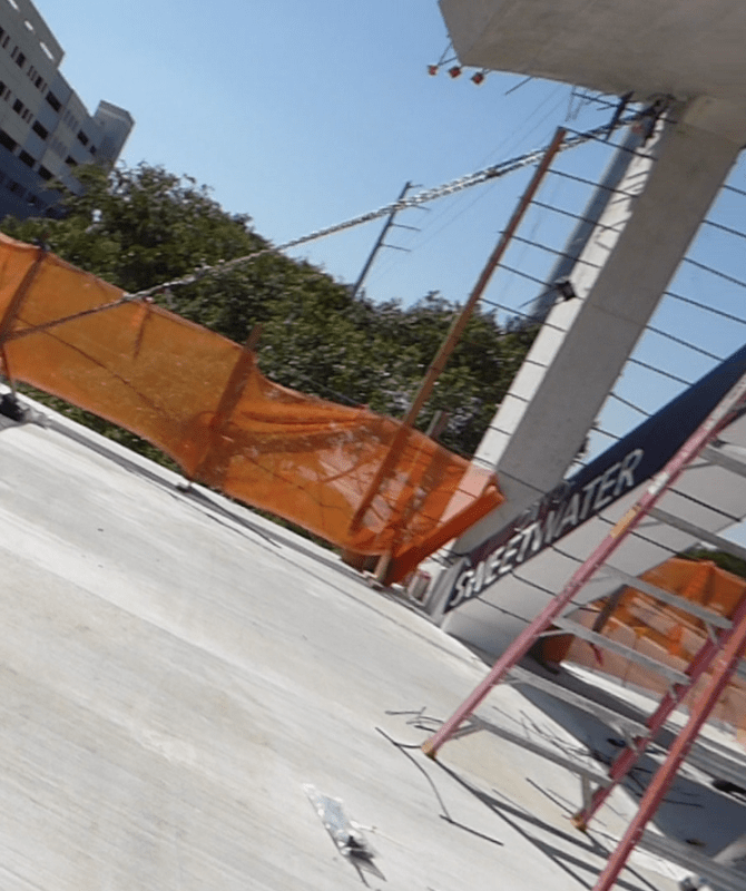
Thanks for your photos on the two bridge ends.

It now seems

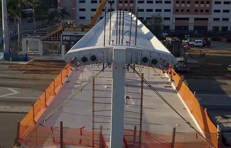
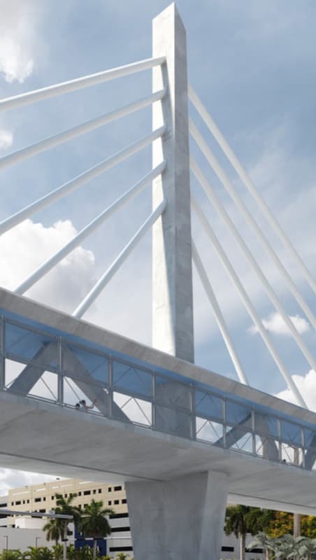
(1) The 6 PT strands have been reduced to 4.
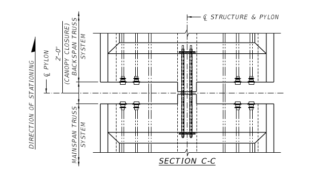
(2) The unused 2 outer strand canopy positions may have been used for connecting the drainage between the two spans.
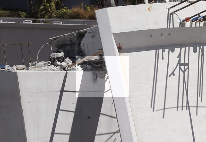
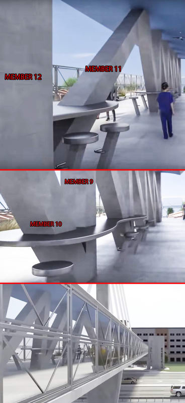
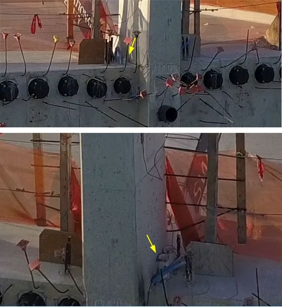
(3) Blister on top of #10-11 was sealed prior to the collapse

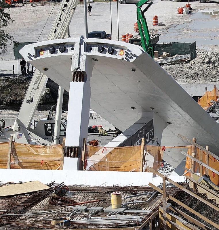
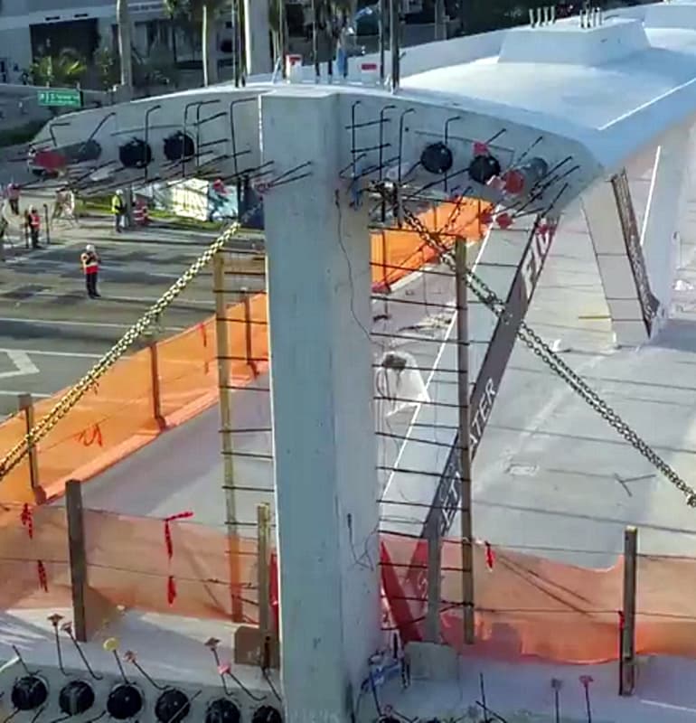
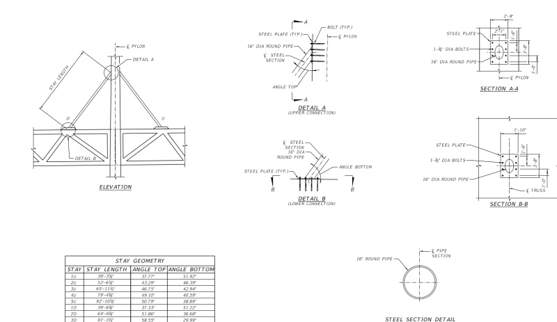
My experience would confirm LittleInch query of the extra rebar or starter bars at the north canopy. The drawings show #12 has a 12" extra concrete beyond the deck's edge. This appears to be used for bolting up with the second span which has exactly the same design. The 2x12" void is indicated as (2-0" canopy closure).
Canopy_closure_lrvvqq.png

The same arrangement can be seen on the deck. The sticking out rebar or starters bars should be for the second stage concrete when the 2' closure is filled.

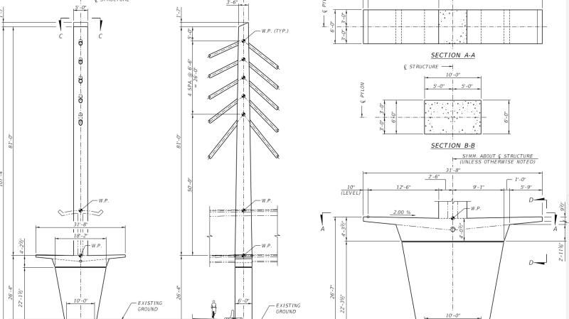
Additionally for constructing the 81' tall by 6' wide by 5' deep pylon, for connecting the stayed pipes, #12 will be enclosed by concrete on 3 sides (east, north & west leaving only its south face as the final finish). This explain why
Pylon_construction_k8jkh2.png

(1) there are 9 vertical starter bars cast below as well above the north edge of the canopy, apparently for providing vertical reinforcing steel continuity between the column below and above the canopy. The 6' by 5' column below the canopy will encase #12 on 3 sides.
FIU12PrePost02_pf7d8b.png

(2) about 14 horizontal bars on the east and south face of #12 (bars are close to the south face and were tied to timber during the move), this should be for the continuity of the horizontal links or stirrups of the pylon which is clearly has to be a reinforced concrete column design.
12_side_starter_bars_fbfaut.png

(3) starter bars sticking out on either side of #12 bottom and away from the PVC pipes found unbroken after the collapse.
gwfiu_11-12-deck_annot_04_cvwvuv.jpg


It would be ironic if the bottom connection of #11/12 with the deck, which some of us are convinced to be a weak link structurally according to the evidence, were proved to be the root cause of the collapse.

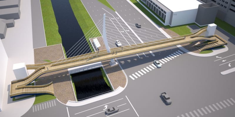
The design was forced to changed by moving the transporter positions into the inner span thereby necessitating additional post-tensions in #2 and #11. It was during the re-adjustment of these tensions that the bridge fell.

Had the bridge survived the readjustment and the first common section of the pylon cast linking the two spans together the weakness of #11/12 connection would be removed as the horizontal forces of the long span would have a reaction to bear against with. The bridge would be safe as original intended.
 
The bottom illustration is clearly different to the others and does look like a cable stayed bridge.

However, not sure it adds much here?

Also that illustration wouldn't work because there are no balancing cables to support the heavier span. you can only have an asymmetric design when the shorter side also contains anchor cables back to ground or to an anchor somewhere.


Remember - More details = better answers
Also: If you get a response it's polite to respond to it.
 
I don't think they were tensioning to close the crack (if the crack was at the base) as there was no one on the lower level to observe the crack.
 
LittleInch,

I thought we are clear that this is not a cable stayed bridge.

The cable is a 16" steel pipe with rather weak connection obviously not intended as a major load carrier.
stell_pipe_stays_jhp99p.png

Some call it a faked cable stayed bridge and NTSB has described its purpose "cosmetic".

It is obvious to me that the bridge has to be designed self sufficient without the pipe stays. Any strong member installed in the stayed section can upset the intended forces in the truss system and that can be dangerous. To me if the bridge were overloaded the bolts on the end of the stayed pipe will have to come out as a warning.

The piper stays are not as stupid as many of us think. This is because a long span bridge can be flexible and if it has a natural frequency below 5Hz it can have dynamic problem in service by the pedestrian traffic. The 10 pipe stays anchored to the two spans can act as soft springs to raise the natural frequency.
natural_freq_equation_ja1uah.png


If we put a spring support in the middle of a beam we increase it vertical stiffness, right? so the natural frequency will be increased if we take the square root of a bigger stiffness (with added springs).
 
As for only 4 of the 6 tendons being placed in the upper canopy, I would venture that the 2 unused positions were for the addition of continuity post-tensioning after both spans were installed and made continuous with concrete. There would then be a tendency for this two-span continuous structure to have tension in the upper canopy over the central pier. The 2 additional tendons would add compression, preventing cracking, and resist negative moments over the pier creating a stronger structure for resisting live loads and other service loads.
 
To paraphrase, posts that say that something has or hasn't happened are always interesting to me, because as we know, there are known knowns; there are things we know we know. We also know there are known unknowns; that is to say we know there are some things we do not know. But there are also unknown unknowns — the ones we don't know we don't know. And if one looks throughout the project, it is the latter category that tend to be the difficult ones.

However, all parties to an NTSB investigation take a vow of silence until the NTSB delivers its final report on an accident. So secret is the process that for some portions of the inquest the partners gather in a secure section of the NTSB building that is equipped with a unique computer system that allows no communication outside the room. Partners at those sessions take notes on color-coded paper that is collected before they leave the room.

What that means to those outside the NTSB investigation is that there is no access to the design documents or the record drawings that the Contractor should have been keeping. There will be no access to any of the construction documentation such as change orders, subcontractors, RFI's, inspections, shop drawings, submittals, lessons learned, training, etc.

Despite that many of the posters envision themselves as being the engineering equivalent of Hercule Poirot, the reveal for this mysterious failure will occur only when the NTSB releases the report. That is because of the fact that most of the clues are secret. Unlike Hercule Poirot, no one on this site has access to the secrets.

I would suggest that future posters keep the NTSB accident investigation process in mind when the urge to post something comes to mind as not much new information has been added to the discussion since immediately after the event.
 
Things we know we know
The Bridge fell down and killed 6 people and injured many more. Let's not forget this has affected lots of people who were in a 1 in 10 million chance of being in the wrong place at the wrong time.
The collapse happened very quickly and hence finding a root cause at this time with the limited public data available is next to impossible.
The collapse happened at the Northern end within the last bay containing members 10, 11 & 12(the end vertical member).
There was a crew working on the bridge doing something with the PT rods in member 11
There was a crack somewhere in the North end of the bridge
That crack wasn't deemed serious enough by the construction company to close the road underneath it
The bridge was in structural terms a concrete span, not a cable stayed bridge (the "cables" were going to be mainly cosmetic and non supporting, but could have limited any vibration or bouncing)
The artistic design led to an asymmetrical supporting member design
The bridge was in essence a rigid concrete beam with some interesting features making analysis more complex
The second span on the North side wasn't yet installed
At some point the bridge span was lengthened and the north pier moved to allow for a future road widening
Moving the pier meant that the two transporters moved inboard from the ends ( the concept design) requiring special re-inforcement of members 2 and 11 to take account of loads seen during movement of the bridge only.

Things we know we don't know for certain
Well virtually everything else:
What the crew were actually doing at the time of collapse.
Whether the initial crack had anything to do with the collapse.
Whether member 11 failed at the top or bottom or was just caught in collateral damage.
Whether the upper or lower bridge flanges failed first or broke as a result of failure of something else maybe a few milliseconds earlier.
What the final design was or what the design analysis showed.
Whether there was any failure in any tendons or PT rods.
Whether planned reinforcement details were altered on site and other ducts installed.
Whether the span had been adequately analysed for its temporary condition before the second span and tower / "cables" were installed.

Things we don't yet know we don't know
Everything that has been handed to the NTSB or disclosed in testimony

We can speculate on these items above until the final report is written and given the probable lack of real time data, even that may never pin down 100% a single cause only one or maybe several probable causes.
Many of the potential causes have been identified in the many many posts in parts I to V. People coming late to this post are clearly not reading through 900+ posts and so the debate has started to get very circular and mainly just rehashing old ground.

It will start again on the release of the data from the NTSB.

This post has been authorised by group administration as a simple summary of where we are.
People are encouraged to read the earlier posts which should help answer most questions.
 
Status
Not open for further replies.
Back
Top