Continue to Site

Eng-Tips is the largest engineering community on the Internet

Intelligent Work Forums for Engineering Professionals

  • Congratulations KootK on being selected by the Eng-Tips community for having the most helpful posts in the forums last week. Way to Go!

Miami Pedestrian Bridge, Part VIII 80

Status
Not open for further replies.

JAE

Structural
Jun 27, 2000
15,460
A continuation of our discussion of this failure. Best to read the other threads first to avoid rehashing things already discussed.

Part I
thread815-436595

Part II
thread815-436699

Part III
thread815-436802

Part IV
thread815-436924

Part V
thread815-437029

Part VI
thread815-438451

Part VII
thread815-438966


Check out Eng-Tips Forum's Policies here:
faq731-376
 
Replies continue below

Recommended for you

Thanks for the answer. I didn't phrase the question very well. Putting bridges aside for a moment....
Does anyone know if the shear strength of a concrete "cold joint" is different than the shear strength of a solid block of concrete? Intuitively it would seem likely it would not be the same, but I expect it depends on a variety of factors including how much the first pour has cured before the second pour is made. My question stems from the excellent information in this thread about the FIU Bridge construction using a "cold joint" at the junction of the lower end of diagonal 11 and the walkway. It seems essential that the diagonal be properly bonded to the walkway and it would seem to make a difference whether these two pieces were connected with a "cold joint" or a continuous pour. There was a very large horizontal component of force on this joint (the horizontal component of the compression force in diagonal 11) and I am wondering if the engineers over estimated the shear strength of the concrete that composed that joint because they failed to recognize the field construction had to pour the walkway and diagonal in two different pours. Thanks for your patience.
 
According to the Miami Herald article from June 14, 2018, it's apparent that the Herald's request for additional information from the parties involved was granted, as it's stated within the article that nearly 2,000 pages of calcs were reviewed by several engineers. But where are these calculations? What were the terms of the release? Are there legal restrictions to full disclosure at this time? If this was a freedom of information-like release, why weren't these calcs made public?

Could someone here please explain this to me, or could someone from the Miami Herald please speak to this issue (the Herald article was extremely vague on this point). It seems to me that a perfect way to kill, or control, a story is to request info, then once you've obtained it release it only to a select group of individuals.
 
TheGreenLama... when this first came out, I sent an eMail to one of the people responsible for the article... no response.

Dik
 
Dik,

Thanks for the note. This is a link to the article from the Herald, June 4, about their request to access records: Link.

Mary Ellen Klas (meklas@miamiherald.com), Andres Viglucci (aviglucci@miamiherald.com), Nicholas Nehamas (nnehamas@miamiherald.com), and the Miami Herald, any response to the engineers at Engineering.com?
 
Andres Viglucci (aviglucci@miamiherald.com) was the guy I sent the query to...

Dik
 
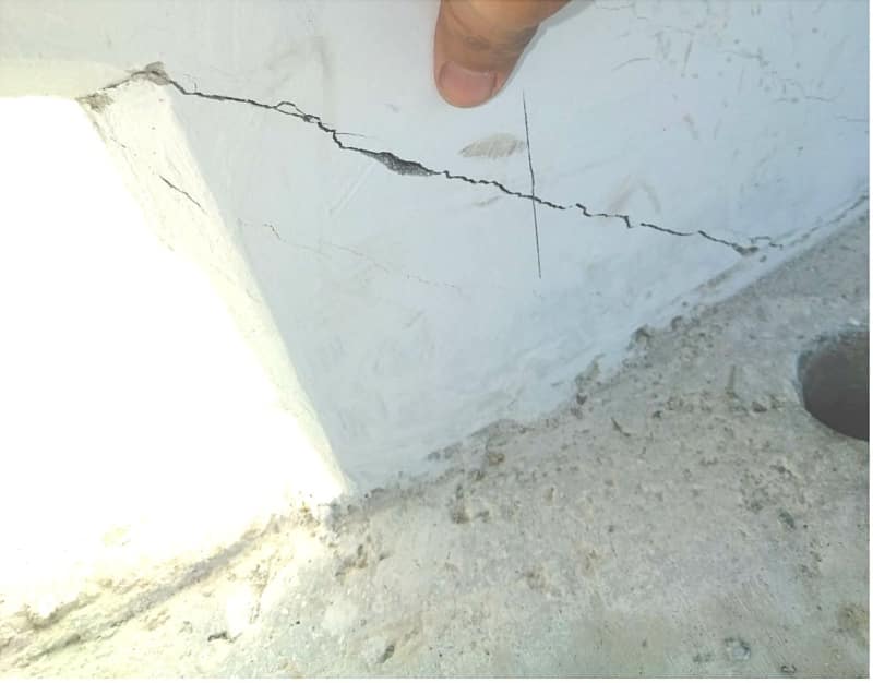
Tomkat: I can't answer your question about cold joint strength (details outside my field), but it's been discussed. I'd assumed #11/12 slid off the end of deck after breaking at cold joint, but recently someone posted a different view of #12's end that shows it broke below the cold joint (which held). The 'leaked' photo showing cracks at base of #11 after shoring was removed shows a crack traveling along the cold joint.

pier-top_view_spaai2.jpg

4j-bcs_sjnt1h.jpg
 
About documentation. This was the best/detailed article.
It sounds like they made a basic public records request for the 2000 pages of calculations.
"The Herald obtained the structural calculations and design plans through a public records request and shared them with the engineers. Howell and Beck, who both have expertise in bridge design and structural engineering, analyzed the plans and calculations independently but came to similar conclusions."

but I'm not sure if this (further down article) means the calcs are no longer accessible by the public:
"Unless you’re part of the investigative team, you may not be privy to all the information.”
"That information is no longer accessible to the public, however. The NTSB has severely restricted access to records related to the accident, leading the Herald to file a lawsuit demanding access to documents that were previously available for public review under Florida public records laws."

This is new from a lawyer. Bottom line is the NTSB is supposed to write a document to say if they want to be party to MH suit, and if not, the judge will rule on whether info between Fed 19 and Mar 15 before the span fell can be released (especially minutes from the meeting about cracks the morning before collapse). Is the same place they were weeks ago when the judge asked NTSB to show up (they didn't but wrote a letter).
 
Chris,

Thanks for the link to the July 5th article in Roads & Bridges. It reads like the Herald has received documents that were created on or before Feb. 19, and that the lawsuit is to try and gain access to material between Feb. 19 and the collapse. At least that's my interpretation. If so, it implies that they have received the design calculations from FDOT, separate from the lawsuit, and for some reason are only letting select people have access to them. What would be their motivation for doing this?

I believe that the St Augustine article is nothing but a copy of the earlier Herald article.
 
FDOT said:
DOT produced documents created on or before Feb. 19—a little less than a month before the collapse—but nothing thereafter, including during the crucial days leading up to the collapse. FDOT’s refusal to produce documents originating after Feb. 19 was the result of a written directive it received from the NTSB

Even though they claim 'no involvement'... I betcha they are in it up to their kazoo... Maybe protecting themselves?

Dik
 
I did a quick critique on an article showing the FDOT's involvement, only to learn that it was for a different project.

Does anyone have a copy of the document that pertains to this project? I couldn't find my reply in the earlier parts of this thread.

Dik
 
chris snyder (Electrical) said:
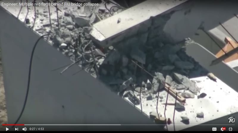
recently someone posted a different view of #12's end
This is a frame from Engineer Multiple red flags behind fiu bridge collapse
It looks to me as though the rebar for the tower (or the diaphragm for the north span?) is intact behind #12 lying on the pier?
Thank you Chris for bring this to our attention.
 
It was, and still is a very interesting discussion, but somehow concentrating on the mode of the collapse, instead on the real reasons leading to this tragic accident.
It is obvious that the bridge was under designed as it failed under dead load alone. So, it’s apparent that there was a major design error overlooked by all involved parties.
As I posted before, the code and design guide used to design this bridge were leading to the seriously “undernourished” structure with unacceptable safety factor, or, as proven by the events, to failure under self-weight.
As on the typical well-founded project, a lot of studies were done such as the study of the loading. Unfortunately, no studies were conducted for the load factors to be used in the design, so typical AASHTO's were likely used, applicable to highway bridges and pedestrian crossings with light weight (steel) structures. The attached article presents some thoughts on the subject, as well as commonly used factors for different types of structures, and explains the risks associated with this approach.
Equally critical, in my opinion, was the methodology used in the design for shear stresses. The current code approach is to carry the excess stresses on the steel, using some fancy formulas, where the old approach was to carry all shear forces via reinforcement, when the allowable shear stresses where exceeded, and always use this approach in the support or anchorage zones.
Perhaps that the secret so closely guarded by NTSB? That the bridge was designed as per AASHTO and “Design Guide for Pedestrian Bridges” without major deviations?
 
 https://files.engineering.com/getfile.aspx?folder=b768b6d4-fda3-4338-baa5-bf478b80b89c&file=History_of_Safety_Factors.pdf
An important reminder: there is no "slow-motion" video. The original truck-cam video was shot at approximately 5fps, or one frame every 0.2 seconds, and had a resolution of 1280x720 pixels. This video was then processed to CREATE THE ILLUSION of zooming and slow-motion. The "zooming" was performed by CREATING in-between pixels, probably by simple linear interpolation, so a small center section appeared larger. The "slow-motion" was performed by CREATING multiple in-between frames with advanced 3D (X,Y,time) interpolation routines that recognize primative shapes and patterns in consecutive frames.

These techniques can produce a remarkably realistic interpretation of an event, as long as the event being filmed has dynamics that are relatively slow compared to the original video frame rate. When this is true, the CALCULATED in-between pixels and frames will create an ILLUSION that matches up very closely with reality.

In this scenario, however, we are dealing with with an extremely rapid series of explosive non-linear events that occurred on a millisecond or microsecond timescale in which 0.2 seconds is a lifetime. As a simple example, a car traveling at 60 mph, or 88 feet per second, travels 17.6 feet in 0.2 seconds. If you filmed that car driving into a concrete barrier at 5fps, you'd only record one or two frames of the impact, and you simply don't have enough information to process those frames into a video that portrays the crash realistically. That same reasoning should be applied to the truck-cam video.

 
Has this been suggested yet?
The compressive strength of the diagonal member was exceeded.
The lower part of the diagonal member crumbled under compression.
With part of the diagonal member crumbled, the member ceased to be a viable structural mamber.
Gravity took over.
As the bridge collapsed, the shortened remnant of the diagonal punched into the vertical member inducing the shear failure.
At the same time, more of the diagonal member may have crumbled.
The final position of the hydraulic jack indicates that the diagonal member is considerably shorter than originally.
My main point is that the initial failure may have been compressive failure rather than a shear failure.
This suggestion is supported by reports that the initial failure occured during an operation that increased the compression stress on the diagonal member.

Bill
--------------------
"Why not the best?"
Jimmy Carter
 
waross, in looking at the way the post-tension bars were installed, they acted like anchors in the deck, below the shear line of observed cracks. If one were to put a cable alongside the diagonal for the purpose of pulling it off the end of the deck one would anchor it just the same way. In an early post I took a shot that the compression load in that diagonal was approximately the full weight of the bridge; the total compression stress was from that was in the mid 4ksi range for concrete that was supposed to take 8.5 ksi minimum. The additional tension was 5-10% of the dead load (sofa-cushion estimate).

From this I have since concluded that the most likely failure was to continue to fail the connection that had already failed - the shear line between the diagonal and the deck. Only an inch of relative movement would exceed what the rebar bridging that connection would be able to take. Whether the rebar failed in pure shear or because of excess tension as the embedded ends were displaced, I don't know, but the overall failure looks to be entirely from a loss of shear capability.
 
From earlier threads and information there are two tensioning bars in member 11, one high and one low. Apparently the top bar had been further tensioned and it was during the tensioning of the lower bar when the failure occurred.

The top bar remained in place, but the bottom bar, which was anchored into the bottom base was ripped out of the member 11 during the collapse thus showing that, at some point during the collapse, member 11 became detached from its connection to the base. This ripping out essentially shortened the bar leading to the tensioner sticking out the top.

Now whether this was cause or effect is not clear, but many here believe that the extra tension on the bottom bar added to the shear load of the joint between 11,12 and the base leading to a shear failure in that joint, perhaps initially only of a couple of inches, which then lead to a sudden failure of the rest of the structure. Now how that complex joint was designed, analysed and reviewed / approved is probably the key design issue here as wiktor states. On the design data available and evidenced by the cracks seen, it looks like the weak point and is not over encumbered with re-bar.


Remember - More details = better answers
Also: If you get a response it's polite to respond to it.
 
The Chirajara bridge in Colombia collapsed on January 15, 2018.

On January 31, fifteen days later, a preliminary report was presented explaining the reasons for the ruling.

The report mentioned the desirability of demolishing the opposite side of the bridge.

On March 15, 2018, the FIU pedestrian bridge collapsed.

Because 120 days later there is no preliminary report?
 
They already released a preliminary report.

The NTSB typically investigates for systemic causes into failures, not simply immediate causes and this can take longer. There is also no pressing potential of another collapse of a similar structure because there is no other structure built to these plans. I'm pretty sure the NTSB clearly stated that it would take up to a year before their final report would be issued. Even if they did not, that is the amount of time almost every final report takes; they do not issue any intermediate reports.

 
3DDave... that report and $2.00 will get you a cup of coffee. Report was useless. Taxpayers' money hard (ly) at work.

Dik
 
Status
Not open for further replies.

Part and Inventory Search

Sponsor