OSHA provided a scathing and justified review of process leading up to collapse, but in my opinion, they've muddied the waters with their analysis of the shear-friction plane. What NTSB really needs to do, w.r.t. this shear failure plane, is:
1) Provide a thorough critique of FIGG's calcs;
2) Based on FIGG's calcs, detailing, and existing conditions, they need to describe, step by step, the behavior seen leading up to failure (obviously, shear lag is also a major contributory factor to failure);
3) NTSB also may also want to make design suggestions for shear-friction, as even OSHA's analysis is misleading. It's clear that the concrete surface should have been roughened, and shear-friction steel should be situated entirely within compression zone (more on that below), but it would be good to have NTSB's take on it;
4) And, obviously NTSB should list any code shortcomings.
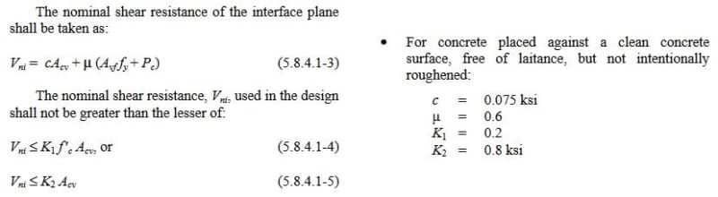
First, how OSHA came to it's conclusion of the 22% deficiency. The equation used, LRFD 5.8.4.1-3, p.422, is the same as was used in FIGG's calcs, except OSHA has included a concrete area component for non-roughened surface, with mu = 0.6 and c = 0.075 ksi, LRFD 5.8.4.3, p.426.
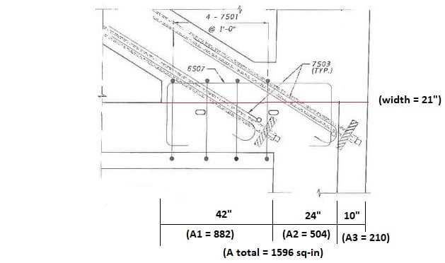
Ac = 76 x 21 = 1596 sq-in
Avf = 9-#7 (0.6) + 3-#11 (1.56) = 10.08 sq-in
Vni = c*Acv + mu*(Avf*Fy + Pc) = 0.075*(1596) + 0.6*(10.08*60 + 705) = 906 k
Vu = 1106 k
% deficient = 100*(1106 - 906) / 906 = 22%
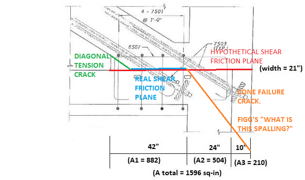
>> Shear-Friction Plane (Acv). Now, the questions with OSHA's approach, and thoughts on a revised assessment of the capacity of the FIGG designed joint. First, separate the shear-friction plane as such:
where A1 corresponds to the diagonal-slab interface, A2 corresponds to the diaphragm-member 12 interface, and A3 corresponds to a section through member 12 that lies outside of diaphragm.
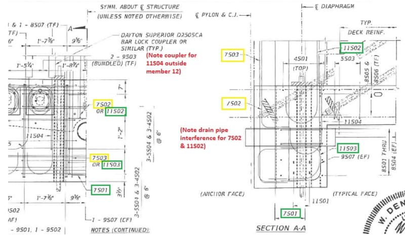
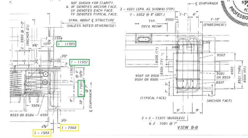
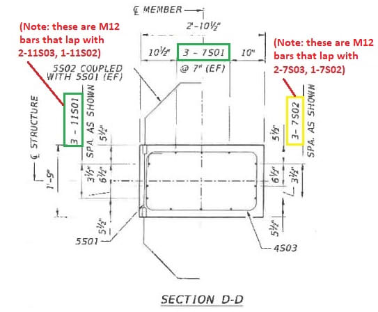
>> Shear Steel (Avf). Next, identify the shear steel within each of these concrete areas, and its availability to assist in shear-friction. Green highlights show bars that certainly would be included, yellow are questionable (Asq):
Area 1: bars 7S01 lack adequate development length; bars 7S03 are inclined in wrong direction (ACI 11.6.4.2, p.191). No steel.
Area 2: 2-11S03, 1-11S02, 4-7S01. Neglect the 2-7S01 bars 10'' from back face, as these lie outside the main diaphragm steel (see notes for Area 3). As = 7.08 sq-in; Asq = 1.2 sq-in.
Area 3: Neglect the 2-7S03 & 1-7S02, as these lie outside the diaphragm steel; Asq = 1.8 sq-in.
Engineering judgement tells me to neglect these "questionable" bars. I would not want to rely on this concrete stub, which extends beyond the confinement steel of the diaphragm, to develop much shear-friction capacity at deck level. But as some will question this decision, below I'll run numbers both with and without Asq.
>> Capacity (Vni). Now, determine capacity:
As has been referenced earlier in thread, the online version of AASHTO LRFD 2012 is used
Link.
In addition, ACI 318 is used for additional reference. Latest version online is ACI 318-11
Link. Note that 318 was completely reorganized into 318-14. I could not find an online version. Correct me if I'm wrong, but I don't believe the Shear-Friction section was altered appreciably from 318-11.
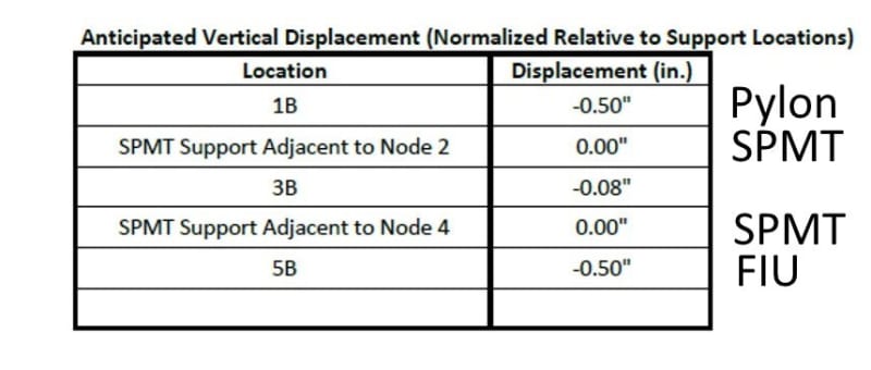
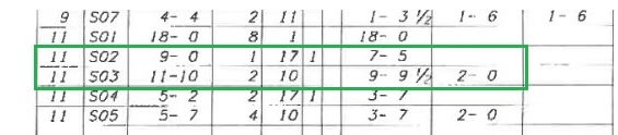
Loads are taken from OSHA report, p.106-8
Link, with H = 1106 k, V = 705 k. It is not directly stated, but I'm assuming this is for "Case 3: PT tendons in main span truss, except member 2 & 11." As was done in OSHA, no load factors or phi factors have been applied. Including these will only make deficiencies noted below worse.
The "shear" steel (Avf) crossing the shear plane is there to develop in tension, thereby maintaining concrete contact across the crack joint, LRFD C5.8.4.1, p.421, and ACI R11.6.3, p.190. It's also stated that any additional permanent clamping force can be utilized to offset the strains that will develop in this steel, LRFD 5.8.4.1, p.423, and ACI R11.6.7, p.192. My interpretation of this allowance is that only the steel w/i the concrete area that sees this permanent clamping force should be able to take advantage of this reduction. In my opinion, only Area 1 will see this force. OSHA has applied this clamping force to steel in Areas 1-3. I believe this is an oversight on their part.
It's already been shown elsewhere that the steel in Area 1 is not long enough to develop properly in tension. This begs the question--If we have "no" shear steel in Area 1, should we then be allowed to develop Acv, the concrete area in shear? OSHA has included it. We do have a clamping force in Area1, so certainly concrete shear resistance is going to develop, but the codes don't address this unusual condition. Below, I've run numbers for both assumptions.
For the stub area of member 12:
For the same reason stated above for Area 3 steel, I would neglect this concrete area (Acv) as well when determining a shear-friction capacity. But, again, I'll run numbers both with and without this area.
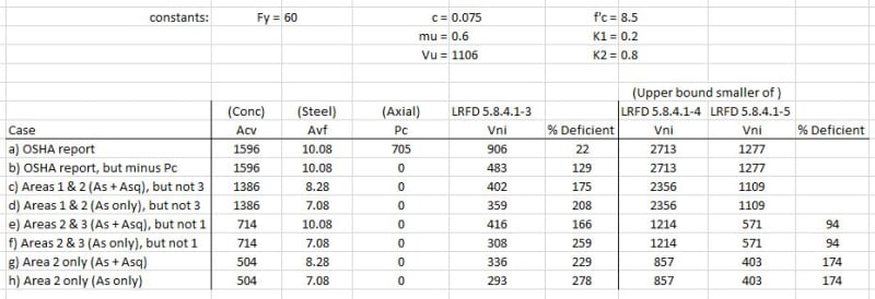
To restate the LRFD eqns again:
Capacity spreadsheet:
The bottom line then, in my opinion, is that only cases (d) and (h) are viable. For (d), however, it's hard to get away from the permanent clamping force acting on the concrete, but w/o adequate reinforcement I think you have to. So, rather than being 22% deficient in shear-friction, as OSHA has stated, I would instead say "the demand is 278% above the available strength." That's quite a difference.
One final point. Whether or not to take into account member 12 loads. OSHA did not. I believe they should have at least mentioned their reasoning for excluding. All I can find in the codes on this subject is "When moment acts on a shear plane, the flexural tension stresses and flexural compression stresses are in equilibrium. There is no change in the resultant compression Avf*Fy acting across the shear plane and the shear-transfer strength is not changed. It is therefore not necessary to provide additional reinforcement to resist the flexural tension stresses, unless the required flexural tension reinforcement exceeds the amount of shear-transfer reinforcement provided in the flexural tension zone." (ACI R11.6.7, p.192) Seems logical enough--what moments give they also take away. But, as all concrete cross sections are not equal, our concrete stub for instance, future codes may want to be more precise in their wording for moments acting on shear-friction planes.