Continue to Site

Eng-Tips is the largest engineering community on the Internet

Intelligent Work Forums for Engineering Professionals

  • Congratulations KootK on being selected by the Eng-Tips community for having the most helpful posts in the forums last week. Way to Go!

Miami Pedestrian Bridge, Part X 50

Status
Not open for further replies.

JAE

Structural
Jun 27, 2000
15,444
A continuation of our discussion of this failure. Best to read the other threads first to avoid rehashing things already discussed.

Part I
thread815-436595

Part II
thread815-436699

Part III
thread815-436802

Part IV
thread815-436924

Part V
thread815-437029

Part VI
thread815-438451

Part VII
thread815-438966

Part VIII
thread815-440072

Part IX
thread815-451175


Check out Eng-Tips Forum's Policies here:
faq731-376
 
Replies continue below

Recommended for you

SFCharlie - Wasn't "Galloping Gertie" one of the first long-span suspension bridges? You can't always predict what will happened when you're first-of- kind. I lived in Boise at a time back in the 70s or 80s when a new mirrored office complex was erected with two sections that resulted in an inward corner with one wall facing south and the other west. As soon as summer started it began overheating cars and people (and bicyclists, in my case) in the SW parking lot. It wasn't as serious as some other "death ray" snafus I looked up, but it was probably one of the first instances of that problem.
 
Down and dirty instrumentation for the move - without needing a reset.
This thing could have been "instrumented" using 2 (maybe 4) lasers fixed to 1 and 12, offset maybe 2 feet, and with a grid target at the other end. Monitor with a pair of binocs or maybe a camera watching the red dot as it moves. Torsion would have caused horizontal movement of the dot. Of course this is analog in a digital world. But anyone watching could have seen the actual motion, not just numbers on a screen.
Does anyone today remember a plumb bob?
 
Vance Wiley said:
Does anyone today remember a plumb bob?

They could make a very simple tilt-o-meter with a plumb bob centered in by metal ring. Clamp the movement while moving, unclamp it periodically to check lengthwise and side-to-side tilt. Compare results between two setups at SPMT locations and take difference to get span sag and twist. No batteries. No wires. Nothin' but gravity. So simple even George Washington would approve!
 
I added two "new" videos to the Timelapse Playlist. They are actually just original-speed (fast) versions of previously posted videos:

The increased speed makes it easier to see the direction and magnitude of SPMT adjustments during two critical phases of the move.

ADD: The "move" was supposed to happen on a surface that was pre-leveled with an abundance of plywood to eliminate the rough transitions that occured as the SPMTs rolled off a curb at the construction site and then jumped over the center median. See the animation video starting at about 0:52.
 
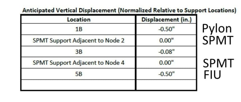
Vance Wiley (Structural) - Thanks for replying to this. I should have posted the vertical displacement determined by Barnhart.

Sag_p70wcc.jpg
 
First time poster on this thread, thanks to all who gathered information and presented ideas.

A few thoughts, the use of shear friction design requires clamping forces to be developed on the face of the presumed crack. In order for clamping forces to develop at least one side must be free enough for the faces to pull together. The clamping forces can then be developed by reinforcement yielding in tension due small displacements along the assumed surface. If either restraint is present or the cracks become large, then the clamping forces are not generated.

For the horizontal reinforcement, very rigid members are provided by both the very deep beam provided by the deck and the bottom of the Type II diaphragm which remained intact. Also, both sides of the Members 11/12/Deck connection had identical horizontal reinforcement, one side would simply oppose the other in a cracked condition, again no clamping.

For an assumed crack at the deck surface and just below the deck, horizontal reinforcement would not have provided any shear friction resistance even if it were able to mobilize.

Vertical reinforcement crossing the horizontal deck surface would have at least initially been capable of providing shear friction. However, significant amounts of the vertical reinforcement does not appear to be properly developed. Also, as the cracks in the deck formed, the gap depth between the top surface and the bottom surface would increase the vertical length between the top shear plane and the bottom shear plane of the reinforcement, requiring ever increasing horizontal movements to generate tensile yield of the reinforcement.
 
Vance Willey said:
I had forgotten the post you reference but I thought a similar post with "V" shaped diagonals wrapping the 11/12 node had been posted by 40YE. Now I see he has apparently removed his posts - I did a search and did not find one.

Vance Willey, you won't find my posts by searching 40YearsExperience. Rather, FortyYearsExperience.

I did not advocate using any drawings showing "V" shaped ties -- that was someone else with whom I am in 100% agreement.

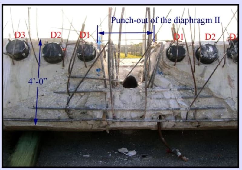
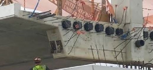
However, I have repeatedly stated that ZERO square inches of tensile rods were provided for tying diagonal #11 to the deck. The photograph below demonstrates this fact with brilliant clarity. One can see there is NOT ONE SQUARE INCH OF STEEL provided to tie #11 to the deck. The designers totally misconceptualized an elementary aspect of the design.

PunchOut_jivhhg.jpg
 
OSHA provided a scathing and justified review of process leading up to collapse, but in my opinion, they've muddied the waters with their analysis of the shear-friction plane. What NTSB really needs to do, w.r.t. this shear failure plane, is:
1) Provide a thorough critique of FIGG's calcs;
2) Based on FIGG's calcs, detailing, and existing conditions, they need to describe, step by step, the behavior seen leading up to failure (obviously, shear lag is also a major contributory factor to failure);
3) NTSB also may also want to make design suggestions for shear-friction, as even OSHA's analysis is misleading. It's clear that the concrete surface should have been roughened, and shear-friction steel should be situated entirely within compression zone (more on that below), but it would be good to have NTSB's take on it;
4) And, obviously NTSB should list any code shortcomings.

First, how OSHA came to it's conclusion of the 22% deficiency. The equation used, LRFD 5.8.4.1-3, p.422, is the same as was used in FIGG's calcs, except OSHA has included a concrete area component for non-roughened surface, with mu = 0.6 and c = 0.075 ksi, LRFD 5.8.4.3, p.426.
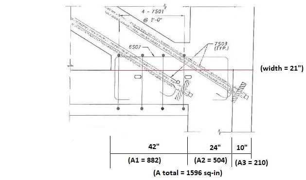
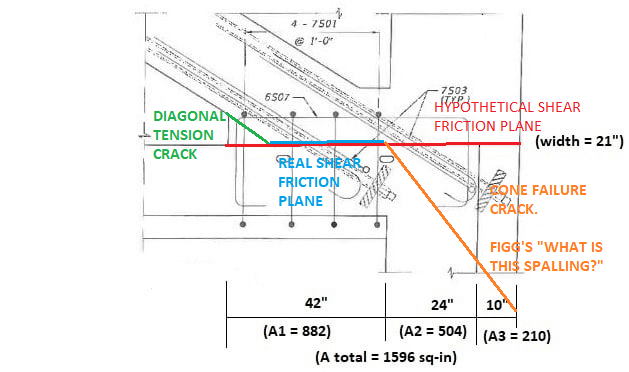
Ac = 76 x 21 = 1596 sq-in
Avf = 9-#7 (0.6) + 3-#11 (1.56) = 10.08 sq-in
Vni = c*Acv + mu*(Avf*Fy + Pc) = 0.075*(1596) + 0.6*(10.08*60 + 705) = 906 k
Vu = 1106 k
% deficient = 100*(1106 - 906) / 906 = 22%

>> Shear-Friction Plane (Acv).
Now, the questions with OSHA's approach, and thoughts on a revised assessment of the capacity of the FIGG designed joint. First, separate the shear-friction plane as such:
OSHA1_cnxkrm.jpg

where A1 corresponds to the diagonal-slab interface, A2 corresponds to the diaphragm-member 12 interface, and A3 corresponds to a section through member 12 that lies outside of diaphragm.

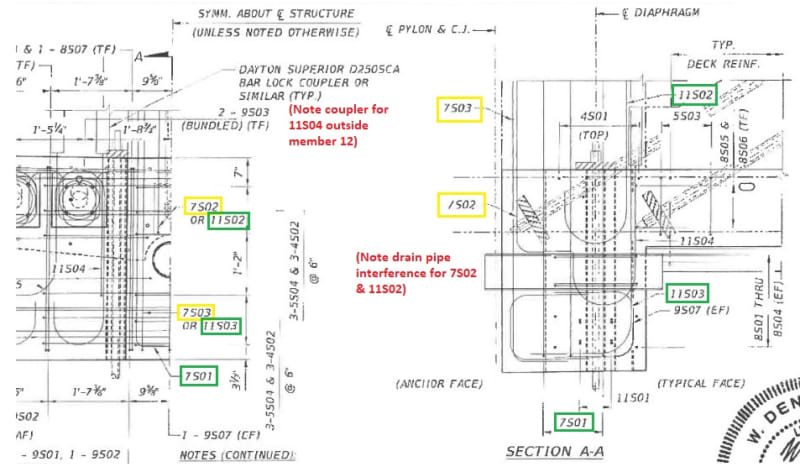
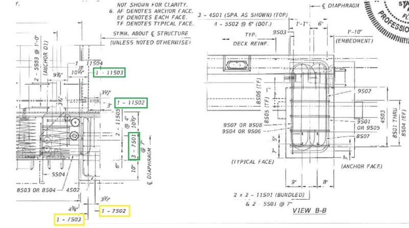
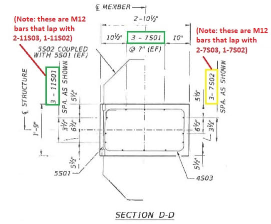
>> Shear Steel (Avf). Next, identify the shear steel within each of these concrete areas, and its availability to assist in shear-friction. Green highlights show bars that certainly would be included, yellow are questionable (Asq):
OSHA2_jpwtog.jpg

OSHA3_tid250.jpg

OSHA4_uigd3d.jpg

OSHA5_rt76bk.jpg

Area 1: bars 7S01 lack adequate development length; bars 7S03 are inclined in wrong direction (ACI 11.6.4.2, p.191). No steel.
Area 2: 2-11S03, 1-11S02, 4-7S01. Neglect the 2-7S01 bars 10'' from back face, as these lie outside the main diaphragm steel (see notes for Area 3). As = 7.08 sq-in; Asq = 1.2 sq-in.
Area 3: Neglect the 2-7S03 & 1-7S02, as these lie outside the diaphragm steel; Asq = 1.8 sq-in.
Engineering judgement tells me to neglect these "questionable" bars. I would not want to rely on this concrete stub, which extends beyond the confinement steel of the diaphragm, to develop much shear-friction capacity at deck level. But as some will question this decision, below I'll run numbers both with and without Asq.

>> Capacity (Vni). Now, determine capacity:
As has been referenced earlier in thread, the online version of AASHTO LRFD 2012 is used Link.
In addition, ACI 318 is used for additional reference. Latest version online is ACI 318-11 Link. Note that 318 was completely reorganized into 318-14. I could not find an online version. Correct me if I'm wrong, but I don't believe the Shear-Friction section was altered appreciably from 318-11.
Loads are taken from OSHA report, p.106-8 Link, with H = 1106 k, V = 705 k. It is not directly stated, but I'm assuming this is for "Case 3: PT tendons in main span truss, except member 2 & 11." As was done in OSHA, no load factors or phi factors have been applied. Including these will only make deficiencies noted below worse.

The "shear" steel (Avf) crossing the shear plane is there to develop in tension, thereby maintaining concrete contact across the crack joint, LRFD C5.8.4.1, p.421, and ACI R11.6.3, p.190. It's also stated that any additional permanent clamping force can be utilized to offset the strains that will develop in this steel, LRFD 5.8.4.1, p.423, and ACI R11.6.7, p.192. My interpretation of this allowance is that only the steel w/i the concrete area that sees this permanent clamping force should be able to take advantage of this reduction. In my opinion, only Area 1 will see this force. OSHA has applied this clamping force to steel in Areas 1-3. I believe this is an oversight on their part.

It's already been shown elsewhere that the steel in Area 1 is not long enough to develop properly in tension. This begs the question--If we have "no" shear steel in Area 1, should we then be allowed to develop Acv, the concrete area in shear? OSHA has included it. We do have a clamping force in Area1, so certainly concrete shear resistance is going to develop, but the codes don't address this unusual condition. Below, I've run numbers for both assumptions.

For the stub area of member 12:
OSHA6_ceepm6.jpg

For the same reason stated above for Area 3 steel, I would neglect this concrete area (Acv) as well when determining a shear-friction capacity. But, again, I'll run numbers both with and without this area.

To restate the LRFD eqns again:
OSHA7_uffnqk.jpg


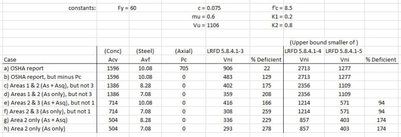
Capacity spreadsheet:
OSHA8_ub867i.jpg


The bottom line then, in my opinion, is that only cases (d) and (h) are viable. For (d), however, it's hard to get away from the permanent clamping force acting on the concrete, but w/o adequate reinforcement I think you have to. So, rather than being 22% deficient in shear-friction, as OSHA has stated, I would instead say "the demand is 278% above the available strength." That's quite a difference.

One final point. Whether or not to take into account member 12 loads. OSHA did not. I believe they should have at least mentioned their reasoning for excluding. All I can find in the codes on this subject is "When moment acts on a shear plane, the flexural tension stresses and flexural compression stresses are in equilibrium. There is no change in the resultant compression Avf*Fy acting across the shear plane and the shear-transfer strength is not changed. It is therefore not necessary to provide additional reinforcement to resist the flexural tension stresses, unless the required flexural tension reinforcement exceeds the amount of shear-transfer reinforcement provided in the flexural tension zone." (ACI R11.6.7, p.192) Seems logical enough--what moments give they also take away. But, as all concrete cross sections are not equal, our concrete stub for instance, future codes may want to be more precise in their wording for moments acting on shear-friction planes.
 
Fortyyearsexperience said:
However, I have repeatedly stated that ZERO square inches of tensile rods were provided for tying diagonal #11 to the deck. The photograph below demonstrates this fact with brilliant clarity. One can see there is NOT ONE SQUARE INCH OF STEEL provided to tie #11 to the deck. The designers totally misconceptualized an elementary aspect of the design.

Yes it does look like an unreinforced punching shear failure. The strut has simply burst out the back of the deck.

In my opinion these shear friction numbers are a bit of a nonsense, because they only give you the capacity of a very specific assumed failure mode, which in this case doesn’t appear to be the actual failure mode.
 
In response to Tom and FortyYears, and even when the structure gave them nearly a week to prop it up, they crushed the last remaining hope, another astonishing misconceptualization.
 
Based on Design Documents I have been able to find, not final, and the presumed reinforcement in the members from the Design Drawings, it appears reinforcement shop drawings have not been made available yet (if anyone has I link, perhaps I missed the link in a previous post, that would be very helpful).

Member 11 appears to have 8-#7 bars (7S11), one each corner plus one each face. Eight non-contact #7 (7S03) lap splice dowels, two each face, into the deck and diaphragm terminated by 180 degree hooks. The single ties in Member 11 are spaced at 12" on center and stop at the top of concrete between Members 11 and 12 and do not appear to extend from the top of Member 11/12 concrete to the deck, Member 12 or end diaphragm thru the joint at this location. This would result in relatively long lengths of compression bars not supported by ties. There does not appear to be ties around the middle compression bars in Member 11, and no compression ties at all thru the joint.

Photos indicate that the interface between Member 11 and the deck had began to slide horizontally. This would greatly increase the compression stress in the #7 dowel bars that appear to be unsupported by ties. Prior to horizontal movement the stress in the dowels would have been relatively low and limited by strain compatibility with the concrete. Buckling of the dowel bars may be the cause of the spalling that is seen in the photos of Member 11 on the vertical faces. Ties would have been especially critical between the deck and top of the concrete between Members 11 and 12, the deck would have provided some resistance to buckling. Typically column details often include decreased tie spacing near the intersection of members, also not present in documents seen so far.

Compression reinforcement, properly developed, supported, and spliced would directly resist the axial force of Member #11. Compression reinforcement can not be added to tension reinforcement for shear friction, but are deflection compatible across small cracks, a movement parallel to the assumed crack can produce compression in one bar and tension in another. The net clamping force for shear friction can then be determined by a free body diagram for the assumed plane.

Cracking in the deck would reduce the ability of the dowels to develop at the hook, spalling in Member 11 would reduce the ability of the dowel bars and Member 11 main axial reinforcement to transfer and develop the splice properly.
 
Reply to
FortyYearsExperience (Structural)17 Jun 19 21:43
TheGreenLama (Structural)17 Jun 19 21:45
Tomfh (Structural)17 Jun 19 23:07
and especially:
hpl575 (Structural)17 Jun 19 21:18

Thank you for your great posts.

Your observations are spot on to me. I look forward to seeing how future textbooks explain this accident.

I think part of the process of explaining what happened involves stepping away from codes, and calculations for a moment, and just analyze the static and dynamic nature of the structure itself. Put yourself in the shoes of the elements of the structure. Your are Atlas. What is being asked of you and what happens when you try to fulfill that demand. (Edit: Or as TheGreenLama suggested, better if the code is updated as needed.)

Question, hp1575, I really liked your post. Can you continue to expound upon your line of reasoning?

Question, FortyYearsExperience. Why did analysis software not find missing steel? How does this software work?
4. RELIANCE ON 3D FINITE ELEMENT SOFTWARE FOR DESIGN AND DRAWINGS.
Finite element design packages can be incredibly useful in the design of PT structures. We use them frequently ourselves. But in the hands of an inexperienced designer, such programs can lead to lazy design habits, poor quality drawings, and bad designs. Always have an experienced PT designer review the computer’s results and never use drawings produced by a computer program without thorough review.​

FortyYearsExperience, I see in your photo the D1 spirals near node held very well. Members 11/12 did not have anything similar to hold them? What caused 11 to crack? Bending moment? Crushing inside member? Different amounts of slippage across deck? (EDIT: crossed post, hpl575 just explained) Is it feasible EOR in his forty years of experience saw so much benign cracking that he was caught off guard in this case? Also, did not EOR state shoring up deck would just lead to a "false sense of security". I need help re-finding that quote if it does exist.
 
Regarding models (of any system): They need to be checked to assure the assumptions are correct. for example: did the model use separate components for, the deck, the web, the canopy? That tiny bit of concrete between 11 and 12 looks very vulnerable if modeled separate from the deck. Once the models are correctly completed, it should be easy to check all the different configurations.


SF Charlie
Eng-Tips.com Forum Policies
 
This is how I'm picturing the failure cracks and shear plane. Look correct?

BRIDGE_CRACK_q0dk9i.png
 
jrs_87 said:
I look forward to seeing how future textbooks explain this accident.

I think part of the process of explaining what happened involves stepping away from codes, and calculations for a moment, and just analyze the static and dynamic nature of the structure itself.
I agree. Though clear and open analysis should available NOW not a decade after the event once lawyers have taken their pound of flesh.

Also failure analysis comes in a variety of approaches. In the case the most prominent ones to examine is the simple engineering failure. The other one being the system failure be it individual engineers and/or entire organisational dysfunction, or regulatory failure.

(No different with the Boeing 737MAX. The engineering failures are relatively elementary. But the system failures that lead to those engineering failures are already very damning.)
 
What a thread...I have to say there is a certain beauty to reading this thread 'in one go' and seeing how with each post, the picture and context of the tragedy get just a bit clearer. The fact that the main reasons behind the bridge failure gradually emerge in this thread is a testament to what an open source 'investigation' can do, coupled with a well motivated community, especially considering none of you have any financial incentives for looking into this, I assume. So kudos to every poster in this thread. Your effort and time spent are appreciated.

I would just like to reiterate the Brian's point:

Brian Malone said:
I had to go look for the term I was alluding to earlier: groupthink . . . The phenomena has been described and the effects are often documented in hindsight. Link
Possibly, the attendees of the meeting onsite the morning of the collapse just got pulled into an unrecognized condition of groupthink. The confidence and authority of the FIGG presentation, along with each group's hope for a successful outcome for resolving the cracks and indications of failure of the bridge, allowed the obvious not to be recognized or spoken.

As was also mentioned repeatedly before, such a an engineering failure occurs due to technical mistakes (both 'macro' such as the bridge design concept itself and 'micro' such as calculation of required reinforcement at the problematic node). These technical mistakes in turn occur in a political context. At a certain point, at least for me, it becomes very difficult to separate the politics from the science...I often wonder if I, a junior engineer, would have taken action for example regarding the observed cracks and gone over the head of my superior. I do not have an answer and even if I did, I would not be certain I would act that way when being there, in the middle of it. It seems to me there was considerable pressure from higher ups at all stages of the project (for example I imagine negative opinions on the design concept existed and were disregarded; I would also imagine for instance there was considerable pressure not to close down the road). Of course, yes, all is good and clear in theory, an engineer has a certain responsibility, etc. etc. but engineers are people, and people are susceptible to their usual fallacies (amplified by the wrong political environment), as pointed out by Brian. This of course varies from person to person, but a concrete crack looks different if you just see a picture of it (removed from context), or if you look at it after being pushed again and again to meet deadlines, to say all is running smoothly, to hear the crack is nothing important, etc.

Groupthink tends to get negatively connected to or amplified by the concept of diffusion of responsibility, for lack of a better phrase. Coming out of university and into the construction industry, I was stunned by the severity of this. And I do not mean it in a legal way, I am looking at it from more of a psychological perspective (e.g. the excuse the engineer tells himself 'hmmm, the crack did seem bad but my boss said it's ok and anyway it's not up to me'). This is some cases happens the other way around too: the reviewer (i.e. higher up the chain) just spot checks calculations due to lack of time or other factors, in the back of his head thinking no catastrophic mistake could have possibly made it through (e.g. this designer is a well established company, lots of experience, etc.).

Now, because the politics play such a major role, I am of the pessimistic opinion that nothing much can practically be done to lower the chances of something like this repeating in the future. I believe that the main takeaway for engineers everywhere is to much more critical of their superiors and have the willingness to disrupt a project in case their spidey senses are tingling.

 
human909 (Structural)18 Jun 19 03:3, When the 737 MAX is sorted, it will still be a 737. When the FIU bridge is sorted, the replacement will nothing like the old one. Why is that? Or am I wrong? Does not MCM have contractual right to correct the drawings to code and repair the bridge? (I'm being absurd here for the sake of argument.) In a sense the replacement bridge project will reveal all the missteps taken building the old one. It's official name will be "Opposite Bridge"
Sieinfeld The Opposite Episode aired 19 May 1994 "George decides to turn his life around by doing the exact opposite..."

Is it true FIGG owns a private toll bridge? Are technical regulations more strict for private bridges over public land?

OSHA: "Louis Berger employed Adina, a commercially available software, to analyze the structure..."

Is this what Berger used? >
How much does it cost? Is it in wide use for this technical application?
 
Eagleee (Structural)18 Jun 19 09:05

Great post. I would like to add the following.

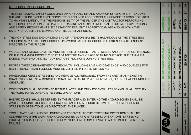
Here is page 5 from 2017_08_11 - Updated Post Tensioning Drawings (SD _00462-1.G).pdf

2019-06-18_2_rw1b2b.png


We are all baffled by EOR's discounting of cracks, but not much mention has been made to discounting of rules. The above guidelines 1 and 5 were clearly not followed. This happens because of the management environment. Everyone has asked why was road not closed. It is precisely because guidelines 1 and 5 were clearly not followed. They are right there on the plans in plain site. Note the mention of unusual sounds on the plans. I find very little mention of the reported cracked-whip sounds in this thread. I know first hand these types sounds are extremely alarming. The cracks were addressed as not a safety concern by EOR. The sounds are totally off the radar.

Reaction to risk is such in humans that some recommend hacking the system by yelling "fire!" instead of "rape!". Over reaction (crying wolf) and resentment of Government/OSHA play a part. My father posted cartoons that mocked OSHA on the office trailer walls in the 70's. In California Prop 65 forces everything to have a cancer / reproductive harm warning sign posted. Even the sign itself has Prop 65 warning. The cancer warning sign causes cancer.

Finally:

What is a PE?

PE origins A must read.
 
Status
Not open for further replies.

Part and Inventory Search

Sponsor