Eng-Tips is the largest engineering community on the Internet

Intelligent Work Forums for Engineering Professionals

  • Congratulations waross on being selected by the Tek-Tips community for having the most helpful posts in the forums last week. Way to Go!

Miami Pedestrian Bridge, Part XIII 81

Status
Not open for further replies.

JAE

Structural
Jun 27, 2000
15,432
0
36
US
A continuation of our discussion of this failure. Best to read the other threads first to avoid rehashing things already discussed.

Part I
thread815-436595

Part II
thread815-436699

Part III
thread815-436802

Part IV
thread815-436924

Part V
thread815-437029

Part VI
thread815-438451

Part VII
thread815-438966

Part VIII
thread815-440072

Part IX
thread815-451175

Part X
thread815-454618

Part XI
thread815-454998

Part XII
thread815-455746


Check out Eng-Tips Forum's Policies here:
faq731-376
 
Replies continue below

Recommended for you

W--e-e-e-e-l-l-l-lllll ------- there is that.
Now that the FHWA/NTSB report is out, criminal negligence charges may develop. You can bet the attorneys have read the reports more carefully than we have.
I can't believe several experienced people observed for real what I saw in a photo and did not pull the plug. I cannot defend that.
I have to hope I would have reacted differently and called for shoring. But that would have been dangerous if began on March 15. It would have taken days to deploy the SMTPs - the outcome was defined before the meeting of March 15 began.
 
The problem is the node blow out was clearly visible, the cracks had opened half inch, and FIGG were on record prior to collapse as knowing they needed to “capture the node”. So it’s past the point where they can say oops.
 
Reading thru the FIGG report, I went huh when I hit the part in recommendations where they felt the need to insert some of their own "propaganda" in a technical report. Then I got to the part where they recommended better hard hats may have reduced/prevented injuries and fatalities. This is probably the most disrespectful thing to the injured and killed I have ever seen in a technical report. Just my thoughts. Inappropriate to post what I really think about that, but my recommendation to FIGG is an "ounce of prevention is worth a pound of cure."
 
Reviewing FIGG report, Party Submission (last item in NTSB docket), Appendix A, WJE report, full scale tests of member of 11. A few observations come to mind.

It would seem to have been better to have used the Florida aggregates in the in the full scale tests rather than create an adjustment factor using small slant cylinder samples.

The time between casting the upper and lower halves of the full scale samples was only one week, where as the time between casting bridge deck and diagonals was closer to three weeks. The bridge was also cast outside and exposed to sunlight on one side for some period of time, formwork appears to have blocked three sides. It is may understanding that the titanium dioxide reacts with UV the create the white appearance. I have not been able to find any literature on what effect the titanium dioxide has on coefficient of friction. It would seem to me that it reduces the friction given that one of benefits stated is that the concrete becomes self cleaning. Maybe it is somewhere in one of the docket items, but all I have been able to find is general guidance on compressive strengths and dosage rates.

The tests do indicate how much additional strength can gained from adhesion as indicated by the significantly higher test values of the uncracked samples comparted to the cracked samples, and that bond between the surfaces is great, until it isn't. The tests also indicate the importance of roughening the surface, but, this was already known.

The tests also indicate that the longitudinal reinforcement bars buckled, this appears to be the case also for member 11 as indicated by the spalls in the surfaces. Wide tie spacing and lack of cross ties for the middle bars likely contributed to the bars buckling.

In big round numbers 21"x24"x8.5ksi = 4,284kips, not accounting for additional strength from the steel reinforcement, average roughened surface test result 2,594kips, unroughened, "as placed", 1,455kips. Makes me wonder why anyone would have a construction joint at such an angle to the axial load.
 
hpl575 said:
...Then I got to the part where they recommended better hard hats may have reduced/prevented injuries and fatalities...

I'd like to see the hard hat that would protect a motorist from the force of a 950-ton bridge falling on their car.

The NTSB report points out that the structure had adequate ductility that it exhibited clear signs of distress before collapsing. Figg as a company and Pate as an individual held responsibility for reading those signs, understanding them, and responding appropriately, the which they did not do.

Here in the US, there is a type of special airworthiness certificate granted to amateur-built aircraft, that allows their operation in public airspace over houses and towns. The presumption is that self-interest motivates operators of such craft to build and operate them prudently, since they will be the first on the scene of any mishap. And it mostly works; accident rates for such aircraft are only slightly greater than their store-bought counterparts. On that basis I hereby propose that for every bridge, the EOR or their official representative be stationed beneath the structure during every maintenance or repair operation undertaken when that space is open to the public.

They can wear whatever kind of hard hat they want.

--Bob K.
 
The middle bars were still straight following the collapse. The surface did not have containment so as the beam compressed and shifted along the deck, the shell had nothing to enforce that motion. I'd say less than 0.06 inches of displacement was required to pop that face off. In a 6 foot span only 0.06 inches of displacement will produce a 1.5 inch rise. The actual amount seemed to be about 0.25 inches, in accordance with 0.002 inches of displacement.
 
Say What?? They tested with a different aggregate? What is that supposed to prove? Jeez!

That is a very good question.

Confinement Steel!
Now to a point made in the WJE report, pages 7 and 8.
FIU_WJE_M11A.JPGA_zcg9tk.jpg

FIU_WJE_11B.jpg_taqtx9.jpg


This would seem to require further discussion. So WJE says 11 and 12 slipped on the deck then 11 split and failed at its lower end, triggering the collapse.
So how did it "root" out the section below the top of the deck? Did the top of 12 get pulled south as node 10/11 dropped and torque out the deep sections over the 8" sleeve? Was it knocked out in an upward direction as the protrusion of 12 past the end of the deck hung up while going over the edge of the pylon?
Certainly points out the folly in restoring the PT in 11 and increasing the compression load in 11 when it was already failing.
Thanks, hpl575
 
So are they planning on issuing helmets before you drive under the bridge and collect them if you make it out the other side? That could actually work - - when motorists get fed up with the hassle they will take a different route and be far safer.
Maybe the turret from an M1A1 Abrams Battle Tank? It would be a little hard on the neck - - -
 
I paused when I read the part about better hard hats too, but as best I know one of the workers on top of the bridge was killed when it fell. I don't think we know any of the details of that, but if it's related to his hard hat flying away when the bottom dropped out from under him and he died of head trauma, then it's a salient point. I think it's more an issue for OSHA to include in their report instead of FIGG, but I guess FIGG thinks that the more trees there are, the harder it is to see the woods.

Brad Waybright

It's all okay as long as it's okay.
 
I was particularly struck by the transcript of the interview of the FIGG stress analyst. He repeatedly distances himself from the bridge design work by asserting that he is an analyst and not a designer, downplays his responsibility as QA manager, and produces this exchange:

"Q. ...when you learned of the cracking, did you ever look at your, the modeling and determine that those cracks were predictable after looking at the modeling?

A. That's a little bit subjective. But there were different stress distribution, so I couldn't say one way or the other."

I don't know about everyone else, but I use FEA quite extensively, and if behavior occurs which was not predicted, we go back to the model and see where the problem is and if we can recreate the behavior that actually happened.

Later on, and i will jump around:

"Q. ...How were the force effects generated from this LUSAS model?

A. ...LUSAS is a stress model. It doesn't report forces easily. You can get reactions at supports pretty easily, but internal forces out of a volume is a little bit more challenging, to say the least..."

Q. Teah, well, I noticed - I'm familiar with the process, so - well, I noticed that it did use the LUSAS model to generate the force effects.

A. Yeah.

Q. So the force effects were calculated by someone. Was that someone you or was somebody else --

A. It was me. Yes, sir."

Wow. Confidence-inspiring.
 
Vance,

The WJE report that you noted (p. 151, seems to be coming at the collapse from several different angles all at once. But the last bullet point seems most relevant:

"Although the collapse was triggered by sudden failure at the base of Member 11, the underlying cause was northward movement of Members 11 and 12 relative to the deck. As described above, the northward movement started with a shear-friction failure below Member 11 that, in turn, led to breakout failure of the north-end diaphragm below Member 12."
 
Thoughts on WJE Report
The WJE report is a pretty good document. It presents tests of sloping construction joints under shear friction.
But they used Chicago Aggregates and not Florida aggregates, a different supplier of Portland cements and Slag cements, and a different Portland cement to Slag cement ratio. Why would you do that? This is a problem with consequences beyond $50 million - how much does it cost to truck a few tons of cement and aggregate to Chicago?
Think of FIGG being able to stand up in court and say we tested the design under full scale tests using EXACTLY the same aggregates, EXACTLY the same cements, and EXACTLY the same quantities of those EXACT components in our testing so these test results directly prove our design is correct.
Now they have to convince the jury their test is even applicable. They will need to say the results are adjusted by some factor so they can apply to the FIU case - which factor will also have to be explained and sold to the jury. Heck, why not just apply an "Its Not My Fault" factor and be done with it?
I did learn something about shear friction action. The concept that reinforcing across the shear plane contributes to the capacity of the joint seems to be validated. The action seems to correlate well with the 45 degree idea of inducing tension in that reinforcing. It was previously presented here that #7 bars at 12D development lengths could result in a stretch of 0.026 inches at 57,000 psi (0.90X yield) and that would be 0.030 inches at yield. The slip of the tested joints was noted to be 0.02 inches at maximum load, suggesting the #7 cross plane reinforcing developed yield at development lengths closer to 8 diameters. I can buy that. That could explain how the 3 pairs of bars in the #7 hoops in node 10/11 developed enough tension to fail. The WJE analysis looks at strut action with bearing to add the contribution of the bend to the anchorage.
I also see that ANY laitance must be removed - and any paste only matrix. The particles in the paste matrix seem far too small to effectively contribute to a perpendicular movement of 0.020 inches and thereby mobilize the cross plane reinforcing.
The test results seem to support FIGG's position that the failure to prepare the surface of the deck under node 11/12 is why the structure collapsed.
Then the Structural Analysis by WJE finds that the capacity of the joint as NOT intentionally roughened was about equal to the demand at the time of collapse. Add to that prior cracking and movements from moving and the results are now clear. Hindsight is 20/20. The WJE analysis seems to be much different than the analysis by FHWA/NTSB which, as I read it, suggests the FIGG calcs are off by almost 100%.
The WJE analysis suggests that correct preparation of the deck surface at node 11/12 would have resulted in a condition that was completely adequate for this phase of the project.
The following is from the WJE report, Page 127.

9 SUMMARY OF FINDINGS AND CONCLUSION
The following summary of findings and conclusion follow from the research and analysis described in
Sections 2 through 8 of this report. The section that relates to each conclusion is indicated.
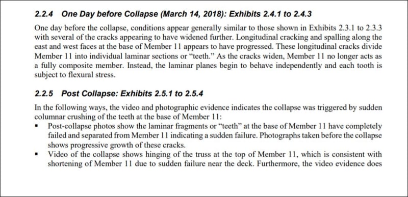
Failure Pattern (Section 2). A debonding and sliding failure at the construction joint below Member 11
led to breakout failure of the north-end diaphragm and ultimately collapse, triggered by sudden crushing of
Member 11 near its base.
Construction Joint Conditions (Section 3).
Despite FIGG’s confirmation to MCM that the FDOT Standard Specifications requiring roughening of the hardened concrete must be followed, the construction joint surface below Members 11 and 12 appeared to have been left in an as-placed (non-roughened), relatively smooth condition.
Interface Shear Transfer Testing (Section 4).
The primary finding from the experimental program is that intentional roughening of the construction joint following FDOT Standard Specifications improved the shear capacity of the cracked interface by a factor of 1.78. This factor reduces by 5 to 13 percent if adjustment for Florida aggregate is made based on slant shear tests. This finding is consistent with relative difference according to the AASHTO Code: the maximum allowable shear stress for a roughened surface (1.5 ksi) is 1.88 times that for a non-roughened surface (0.8 ksi).
Comparison of observed axial strengths of the as-placed (non-roughened) specimens to the calculated force
in Member 11 after the shoring was removed suggests that the construction joint was weakened or at least
partially debonded when the shoring was removed.
More significantly, the axial capacities of the roughened specimens, before or after adjustment for Florida
aggregate, are substantially greater than the calculated axial force in Member 11 at the time of the collapse.
As such, if the construction joint were roughened as required by the FDOT specifications, the collapse
would not have occurred. This conclusion is valid for hardened concrete surfaces intentionally roughened
in accordance with FDOT Standard Specifications even if the surface roughness is considered to be less
than the 1/4 inch amplitude referenced in the AASHTO Code. Also note that this conclusion neglects the
additional capacity from breakout resistance of the north end diaphragm, which if included would provide
additional capacity to the connection.
Structural Analyses (Section 5).
A finite-element model of the main span was developed to determine truss member forces and bending moments during construction.
AASHTO LRFD Design Compliance.
The Member 11/12 deck connection was evaluated in accordance with the AASHTO Code, assuming resistance by shear-friction across the entire construction joint.
Although inconsistent with the actual failure mode, resistance by shear-friction across the entire
construction joint is the likely design assumption. Based on WJE test results, the AASHTO friction
coefficient for a roughened surface (which calls for 1/4-inch roughness amplitude) was assumed. However,
AASHTO does not provide specifics on preparation of the joint (including intentional roughening of
hardened concrete) or how roughness is measured. The FDOT Standard Specifications, as proven by
laboratory testing, achieves the requirements of AASHTO Code. The capacity-to-demand ratio was found
to be 1.09 if AASHTO load modifiers for ductility and redundancy are excluded, and 0.99 if they are
included, indicating compliance with AASHTO design requirements.

The following is WJW Report page 128.

Capacity Analysis for Observed Failure Pattern.
The Member 11/12 deck connection was also evaluated
based on results of the interface shear transfer testing in combination with breakout resistance consistent
with the actual failure pattern, ACI 318 design equations, and related research. The results indicate that the
combined shear-friction and breakout resistance is consistent with the calculated horizontal force in the
Member 11/12 deck connection at the time of the failure. This explains the failure due to the unroughened
construction joint surface.
Evaluation of Peer Review (Section 6).
Berger’s peer review fell far short of their contractual obligations.
In particular, by their own admission, Berger did not even attempt to assess the conditions at the
construction stage shown in the plans that was being built at the time of the collapse, which was required
by their contract. Furthermore, the Berger finite element model could not have been used to reasonably
estimate the forces in the concrete truss members during construction or in the structure’s final
configuration because it did not address the construction phasing.
Evaluation of Twist Exceedances during the Main Span Transport (Section 7).
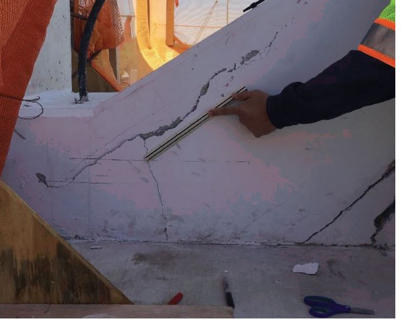
Cracks in the region of the connection of Members 11 and 12 to the deck increased dramatically after the move from the casting yard to the final location, as evidenced by photographs taken before and after the move. The deformations associated with exceeding the established twist limits caused high stresses in the region. Along with other factors, this stress may have been a contributing factor to damage in the region and ultimately to the
collapse.
Re-Stressing of Member 11 (Section 8).
Contrary to FIGG’s instructions, no one closely monitored cracks in the north-end diaphragm during re-stressing of Member 11, even though both MCM and Structural/VSL were aware of the instruction. Also, Structural/VSL’s shop drawings state that stressing operations should stop if existing cracks widen or new cracks are observed. Evidence shows the construction joint was not roughened, so the existing cracks would have widened during re-stressing, and the widening could have been readily detected by several means. In accordance with FIGG’s instruction and Structural/VSL’s awareness of crack monitoring per their shop drawings, widening of the cracks would have required
stopping the re-stressing, thereby preventing the collapse.
Conclusion.
In conclusion, most significant finding from WJE’s research and analysis is that full-scale tests show that if the construction joint below Members 11 and 12 were roughened as required by the FDOT Standard Specifications, the collapse would not have occurred. It is also highly significant that, for the observed failure pattern and relatively smooth as-built condition of the construction joint, the combined shear-friction and breakout resistance determined from testing and analysis is consistent with the calculated horizontal force in the deck connection at the time the failure.

The WJE Report was prepared to support FIGG and seems to present that position pretty well.


Thanks for responsing. I am trying to wrap my mind around the various stages of failure and how they fit together.
I see the top of deck failure first - maybe beginning in the casting yard.
I have previously thought that member 11 gave it up early because of the severe splitting we could see earlier and supported by the recent photos.
We learn from testing by WJE that it takes only about 0.020 inches slip to develop maximum resistance in shear friction. And that at 1/2 inch slip it is over. So at a half inch slip - maybe less - all shear planes had been developed and had failed.
Somewhere between 0.020 inch and 1/2 inch of slip would be a good time for the moments to change in member 11 and the splitting to increase while the joint still has residual capacity to induce axial load in 11, resulting in the loss of capacity in 11, and triggering the failure.
The last two stages were probably a hand off - but it seems that when node 11/12 has failed there would have been a loss of axial force in 11 - except for the upper PT rod.
I am going in a circle here. More thought required.
EDIT ADD:
Or just disregard WJE conclusion and consider damage to 11 as collateral damage from failure of 11/12
 
Zeroing in on this: "Re-Stressing of Member 11 (Section 8). Contrary to FIGG’s instructions, no one closely monitored cracks in the north-end diaphragm during re-stressing of Member 11, even though both MCM and Structural/VSL were aware of the instruction."

This is such an outrageous statement to make! It makes my blood boil just reading it! How many more people would've died if this had action had been followed? What are FIGG and WJE thinking? Sorry for the rant but, IMO, this is beyond the pale.
 
The die was cast and the future foretold ( if someone had read it) before the Friday 15 meeting began. The danger was too great for anyone to be near the thing.
What everyone failed to comprehend is that the cracking was past the 1/2 inch "I'm gonna fail NOW" mode and as Kenny Rogers said it was time to "Know when to Run!"

One more point about the condition of member 11 - with the failure underway and member 11 already splitting, the idea by the EOR to "capture" node 11/12 would not have repaired member 11. It was all over.
 
Figure_6-10_omjmzt.jpg


Here is the photo of the joint area before any concrete was placed. It would be virtually impossible to effectively roughen the surface due to the congestion in that area. And what are those loopy black things? Anything in this area that is not steel or concrete weakens the thing.

Two other observations:
1. The ties in #11 are uniformly spaced above the joint, but at the joint, the spacing increases, and there is no tie at the very bottom where it connects to #12. There could have been one, maybe two more ties in #11 near the bottom, and it would have helped if they would have gone all the way into the deck instead of going around the bottom steel in #11.

2. The top and bottom bars in #11 are lapped immediately above the cold joint. All these bars plus the PT conduits created planes of weakness, that correspond to the cracks that appeared before the final failure.

cracks_a1ybgg.jpg
 
Temporaty Shoring
Too late now, but has anyone seen inflatable bags of a scale that would have held the north end up? A 20 ft square bag would need 17 psi air - is that within the realm of possibility?
Remobilizing the SMPT was days away - an airbag with a long hose seeems like a safe way to support this thing. Tie a rope on the uninflated bag, with a rock on the end, and throw it under. Run around the end and pull the bag in place. Air up thru a hose with connection outside the danger zone.
Of course 3 hours is no enough time - but last Wednesday maybe?
 
Mr. Vance Wyley:
In conclusion, most significant finding from WJE’s research and analysis is that full-scale tests show that if the construction joint below Members 11 and 12 were roughened as required by the FDOT Standard Specifications,
Sorry, but you have been "fooled" by the WJE report.

The "non- 1/4in-roughenning" done in the tests is not the 'roughenning" called for in the FDOT specs when cleaning a joint. The intent of the spec is to leave the joint clean of loose material. Not to chip the joint with a chisel as they did for their so called "roughenning according to FDOT specs". And Florida engineers, designers and contractors know that.

We have to remmember that you have to think like a "Contractor". Chipping the joints requires alot of time and effort that no contractor is going to pay for. So, the engineer (designer) must assume that the joint is smooth (but clean)and apply the corresponding factors in the shear-friction analysis" "non intentionaly roughened" which means no 1/4" magnitude. This is why MCM asked FGG if the joints needed the application of concrete adhesive. And Figg said no: use the FDDOT spec.

FIGG arguments are being laugh at among structural engineers in Florida. But they may convince a jury or those not experienced in Florida bridge construction.

The WJE report is interesting but does not represent the actual situation at the bridge.

What happen is that FIGG forgot to add the note in their erection draawings to roughenn to 1/4" to match the numbers used in the calcs. That is the initial cause of the failure. Still, the structure told everybody it was in trouble and nobody had the "balls" to face FIGG in the meeting, put the foot down and close the roadway: "It was not their responsability"
 
The green Lama

Zeroing in on this: "Re-Stressing of Member 11 (Section 8). Contrary to FIGG’s instructions, no one closely monitored cracks in the north-end diaphragm during re-stressing of Member 11, even though both MCM and Structural/VSL were aware of the instruction."

This is such an outrageous statement to make! It makes my blood boil just reading it! How many more people would've died if this had action had been followed? What are FIGG and WJE thinking? Sorry for the rant but, IMO, this is beyond the pale.


There was a guy next to the strut #11 taking pics and monitoring the cracks. Lucky him he did not die.

Yes, they were closely monitoring the cracks. But the failure was explosive.
 
Vance Wiley said:
One more point about the condition of member 11 - with the failure underway and member 11 already splitting, the idea by the EOR to "capture" node 11/12 would not have repaired member 11. It was all over.

I'm not so sure of that. I think that if Figg had gotten their collective heads out of their butts and actually looked closely at what the cracks were telling them, they might still have snatched victory from the jaws of defeat.

Just as a "what if," consider the possibility that they could construct a heavy steel appliance that attaches to the exposed threads at the ends of the two D1 longitudinal PT tendons, and buttresses against the north face of member 12. Given a sense of urgency and a bunch of petty cash, I bet they could have put that in place in two or three days time. Once installed, it would get encapsulated inside the backspan, and the external profile of the bridge would be unchanged from the original plan. If they had to, they could probably do the same thing at the 1/2 end as well, and add a decorative fillet to conceal it.
 
Status
Not open for further replies.
Back
Top