Eng-Tips is the largest engineering community on the Internet

Intelligent Work Forums for Engineering Professionals

  • Congratulations waross on being selected by the Eng-Tips community for having the most helpful posts in the forums last week. Way to Go!

Miami Pedestrian Bridge, Part XIV 78

Status
Not open for further replies.

JAE

Structural
Jun 27, 2000
15,433
US
A continuation of our discussion of this failure. Best to read the other threads first to avoid rehashing things already discussed.

Part I
thread815-436595

Part II
thread815-436699

Part III
thread815-436802

Part IV
thread815-436924

Part V
thread815-437029

Part VI
thread815-438451

Part VII
thread815-438966

Part VIII
thread815-440072

Part IX
thread815-451175

Part X
thread815-454618

Part XI
thread815-454998

Part XII
thread815-455746

Part XIII
thread815-457935


Replies continue below

Recommended for you

My hope is that the concept of shear-friction will be reexamined. This relatively new, and in my opinion illogical, design method should not have been relied on for such critical joints in a novel structure. Many will say it is not new, but it was not part of ACI 318 when I worked in the US, and is still not part of the Australian code.
 
What does WJE have to say about the fact that the firm hired to perform construction inspection, had advanced the concern, before the diagonals were built, that congestion arising from the deck made roughening of the joint during casting ineffectual?
 
As I recall, and as a recap, the only reference on the drawings regarding construction joint preparation was at a horizontal joint in a pier, with dimensions of about 6 feet by 10 feet.
Finding no specific requirements for the truss joints, the engineering firm overseeing construction requested specific direction in this matter.
FIGG responded by instructing the joint to be prepared to meet FDOT requirements. But FDOT as I read it a year ago gives NO specific direction beyond removal of loose materials and cleaning the joint and FDOT does not specify an amplitude of roughness, normally specified at ¼ inch.
Then, after failure, WJE prepared and tested joints which were prepared to intentional roughness of ¼ inch amplitude and used that as a “woulda – shoulda” joint, implying that their preparations and testing proved the likely results had the FIGG requirement been followed.
But there is a large gap in this logic – somehow they made the jump from FDOT requirements of "clean" to an intentionally roughened amplitude of ¼ inch.
A bit of a “bait and switch” maneuver, it would seem.
 
The end of the deck (the diaphram across the end??) was cracking and moving outward under the diagonal. How can anyone say that roughening the deck to diagonal joint would have stopped that from happening while keeping a straight face? It seemed clear to me that all the pictures of cracks before as well as the after collapse pictures showed that the end of the deck under the diagonal failed, not that the diagonal slid off the deck.
 
The performance of the construction joint at the deck surface is only one step along the way to a disaster. Member 11 was in failure, pipe sleeves beside and below the failed block defined weakened failure planes, reinforcing was inadequate, and NTSB found they used the wrong load for the joint - all these resulted in progressive cracking and failure in progress for days before the actual collapse.
So I am in agreement with you - this joint preparation could not have saved it. The handling of the joint preparation and the double talk attempting to obscure a lack of specificity in the instructions to the job and the subsequent laboratory testing show an attempt to deflect the focus.
Sadly, the EOR did not make an engineering call on March 15.

That would be most prudent at that jucture.
 
WJE has heretofore had a good reputation for forensic work. They have blotted their copybook now.
 
hokie66 (Structural),

I think the usefullness of this forum is there are other experienced professionals who can voice our opinions.

Like Vance Wiley (Structural) pointed out the Member 11/12 has already been separated from the deck so the adhesion at the construction joint is minor if not trivial comparing with the loss of effective concrete at the critical section displaced by the 4 No. of vertical 4" I.D. pipe sleeves, various cable ducts and one large horizontal 8" I.D. embedded drain pipe. These embedded items are the real killer because not only they (1) robbed the section of precious bonding concrete they also (2) obstructed placement of reinforcing bars so desparately needed, (3) created weakness points and paths (stress concentrations) due to their presence and (4) provided sources of defective construction due to the difficulties of compacting concrete in small, tight and confined spaces.

In the update to the preliminary BTSB report on May 23, 2018 NTSB's Fig 1 and 2 show, below the the construction joint, the deck had already developed diagonal shear cracks, typically about 45 degree, in a pattern exactly predicted by FDOT Engineer Tom Andres on Mar 2016 when he first review the preliminary design. The crack on one side was 4" deep shown from the insertion of a tape and appeaed at least 20mm wide. Above the construction joint NTSB showed by Fig 3 Member 11 had a crack 7" deep against by the insertion of a tape. The extensive cracking of Fig 1, 2 and 3 were taken prior to the collapse and also based on them Figg declared the FIU bridge safe! NTSB and most of us were critical of such claim as it shows Figg did not even know the bridge had gone and continued to fiddle with the postensioning rod until the bridge broke up.

The key evidence prior to the collpase shows bridge had suffered fatal and structural damage below and above the construction joint and any suggestion that the adhesion of old deck concret could have hold the bottom of Member 11/12 without separation/failure cannot come from an experienced or qualified reinforced concrete designer. Any engineer experienced in reinforced concrete can confirm it is normal for such a constrcution joint to have minor cracks just by shrinkage in many existing serviceable structures.

 
Thank you Saikee119
I would also note that the WJE modeling did not include the conduits for the post tensioning rods, etc. It also modeled the deck as effectively infinite depth, when in fact the deck failed. They seem to have set out to prove that the un-roughened cold joint was to blame, and saw what they were looking for.

SF Charlie
Eng-Tips.com Forum Policies
 
SFCharlie (Computer),

I haven't followed WJE modelling recently but I know the accuracy of every mathematical model depends on the assumptions used. Rubbish in rubbish out.

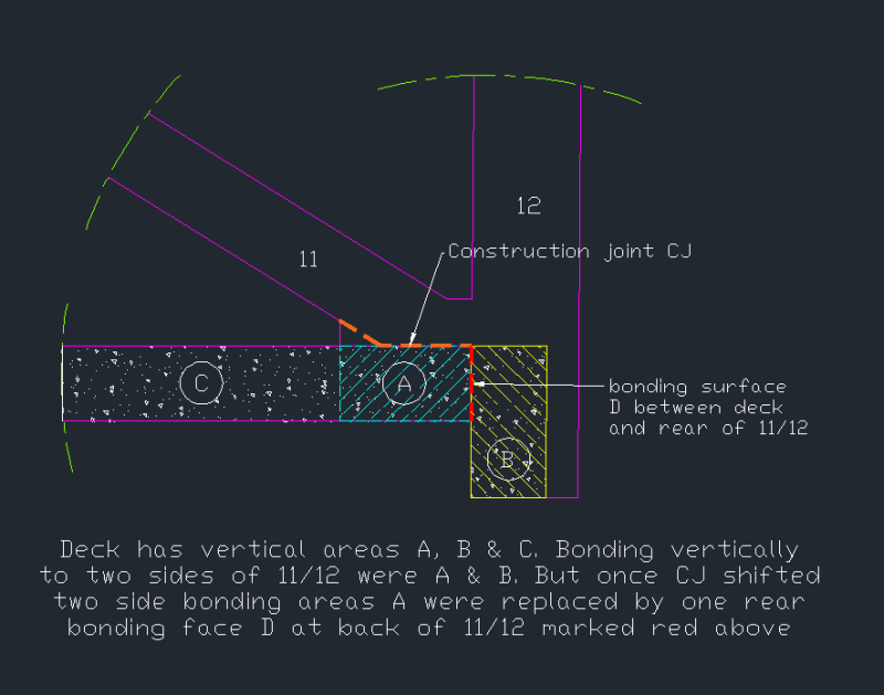
I post the follow sketch to higlight some of the important considerations
2_cycg0t.png

I have shown three section of the deck in A, B and C. C and A were highly stressed laterally by the transverse tendons whereas Member 11/12 was unstressed in the same direction. Thus the interface is prone to crack when there is a major change in stresses in the components. These members were initially held tight together by the PT rods in 11. According to OSHA report 11 has no structural crack at the CJ prior to the bridge removal from the casting yard.

The CJ was seen open up (or cracked) after the bridge had been installed at its final position and the PT rod stress was removed. At this point 11 would have its highest compression load (less only the live load) and it could only hold its position if its joint with the deck did not break.

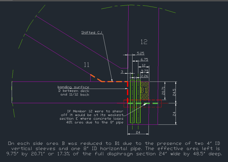
It can be said with certainty in any court of law that the joint in question had already failed structurally prior to the collpase and re-tightening of the PT rods. The following sketch shows the effects from the embedded items.

3_vfwp4k.png


Prior to the collapse we know the CJ had cracked or the interface shifted horizontally. The failed components show the failure plane could include the horizontal CJ indicated by the orange dotted line, a vertical plane between the deck and the bottom of Member 12 (show in red dotted line) and two horizontal plane , in green dotted line on either face of 12) along the embedded 8" drain pipe's centreline. In transverse direction possibly two more vertical planes, on either face of 12, shown as B1 were contributing shear resistance against failure.

OSHA has called it a blow-out failure when the bridge collpased.

The shear resistance of concrete and the shear resistance of rebar across the above dotted line interfaces or plane are the main forces to hold the bridge together. Some enhanced shear resistance from the clamping action may be at play but not much in this failing mode.

The design has a modest but not generous amount of shear steel across the CJ interface. At the deck interface with the front of 12 reinforcement is lacking because of the two PT rod anchors there plus the semi-circular cutout for the drainage pipe had left little room for passing the reinforcement through. The two sides bonding of 12 with the deck, Area maked B1, have been curtailed severely vertically by the 4x4" vertical sleeves and horizontally cut off by the presence of 8" drian pipe.

I have not gone through every steel bar to compute the capacity of this joint but it is a lot weaker than any drawing could reveal if the full set of embedded itmes were not included in the examonation.

Only looking at how little room availabe for inserting rebar so that it can have adequate development lengths, on both sides, then one realises how hopeless is the situation. If WJR could not find how this joint fails then its modeller has not enough practical knowledge of reinforced concrete in the field. If any rebar cannot be anchored adequately in both directions across an interface then that rebar should be written off structurally (for not able to realise its full material stress). In the OSHA report one can find a rich set of examples showing exposed bars with intact hooks and clean lengths which indicate the failures were by bonding and not shear.
 
The horizontal component force in Strut #11 was known to be 1,500 kips (1.5 million pounds) at the time of the design

Back of envelope, to hold 1.5 million pounds in place requires 25 square inches of steel. (before we get onto factors of safety etc.)

NOWHERE in these drawings can we find 25 square inches of steel, let alone that amount being configured to restrain the horizontal force in strut # 11.

And, as saikee119 points out, the small amounts of steel which are visible are too short to provide any development of tension force. Effectively, there is ZERO square inches for meeting the requirement of 25 square inches of tension steel.

So, the FIGG argument is that 1.5 million pounds could have been held in place by cleaning the cold joint better.

HAHAHAHAHAH
 
FortyYearsExperience (Structural),

For Member 11/12 To initiate a failure by pushing out from the deck the concrete has to break along the line of least resistance. Most of the resistance is the shear capacity of the concrete and the rebar from shearing and tensile strengths. Tension is concrete is normally a write-off in RC design unless postensioning is involved.

There are many combinations but the failed bridge has helped us to establish the mode of the blow-out. I have stopped to count the steel bars as the drawings are quite poor in revealing the information. May be the latest drawings with a complete set of bar bending schedule would help.

What is certain many bars if adequately anchored would have to fail by shearing off the circular section or snapped off by tension but not many of those are visible. If the rebar could not hold the node together as a rigid joint then the theoretical models would have little value. The primary failure wasn't in the structural calculations but in the detailing of the rebar because the node was not made rigid enough to perform its structural duty.

NTSB criticised the design for the load and capacity calculation errors. This is equivalent to say the capacity of the node should have been downgraded due to the imperfection of rebar installation (caused by PT rod anchorages, limited concrete dimensions, large amount of embedded pipe sleeves and drain pipe at critical locations creating stress concentrations and load path interruptions).

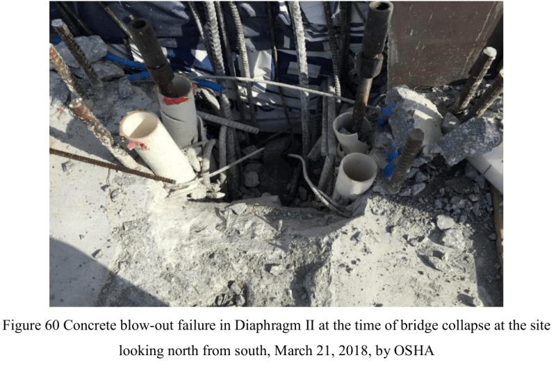
F60_xrau7r.png

The 4 vertical sleeves were in good condition after the bridge broke away. Could the plastic stronger than the reinforced concrete? These sleeves formed a weak spot for Member 11/12 to leave the deck "cleanly".
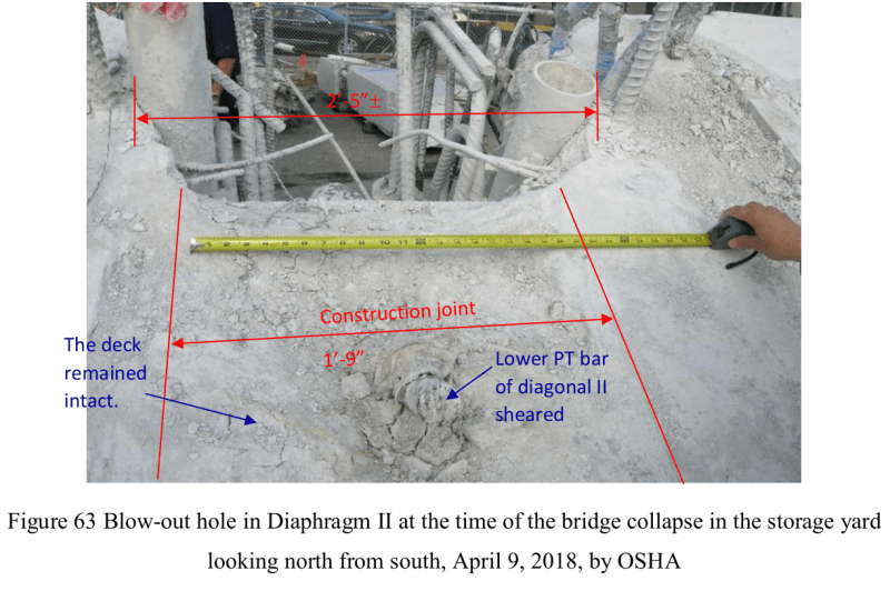
F63_vtnjat.png

All the reinforcement across the CJ had sheared off properly although only a few cross sections could be seen or made out from Fig 63.

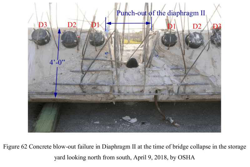
F62_iydwpg.png

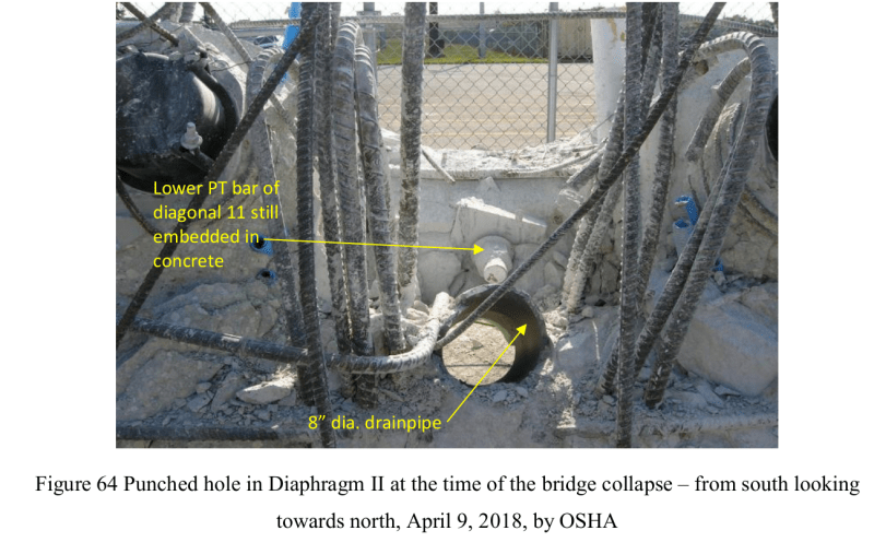
F64_gmrk6x.png


Looking at the above OSHA drawings, showing a massive amount of rebar unable to be gripped soundly by the concrete, it is a waste of time to go the extreme length to prove the concrete adhersion at the CJ if constrcuted perfectly could have made a difference.

Any engineer investigating the 11/12 connection with the deck needs to appreciate the installation of 4 No. of 4" vertical plastic pipe sleeves and one 8" PVC drain pipe have severely compromised the integrity of the rebar in the vicinity by depriving the full development of the concrete bond with the steel bars. In another word there is no use in having sufficient rebar development lengths when there isn't sufficient concrete surrounding the steel bar!
 
Saikee119 said:
It can be said with certainty in any court of law that the joint in question had already failed structurally prior to the collpase and re-tightening of the PT rods.
Yeah, but If I were in any way culpable in all of this, I'd sure hope that all the esoteric talk about an un-roughened CJ might be just enough to convince (or confuse) a juror enough to believe that I didn't belong in prison.
I'm not sure the thought of bringing criminal charges has been dropped yet.

Brad Waybright

It's all okay as long as it's okay.
 
thebard3 (Computer),

A construction joint with concrete poured at different times, resulting unavoidably slightly different shrinkages and creeps, is always a plane of weakness no matter how perfect the construction.

The Fig 63 by OSHA I posted last time in fact shows the performance of the CJ rather well. To any experienced RC professional the construction result looks normal, acceptable, average, no particular bad or good. The shear surafce is quite rough, irregular and deep at places because a significant amount first stage concret had been forcibly removed substantiating a significant amount of successful integration, bond or adhesion with the second stage concrete.

There were altogether 10 vertical bars (2x4x7S01, 2x6S07, see drawing B61) plus 50% of the axial rebar from Member 11 (2x4x7S11+2x7S03, see drawing B40) and one PT rod sheared off cleanly at this CJ.

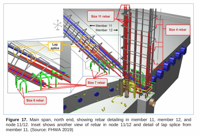
F17_h7ol6d.png


The failure of the connection is actually due to what happens the beyond the CJ to the rear end of Member 12 where the majority of the rebar from Member 12 was exposed and had no bonding concrete. With the exception of a few small diameter bars severed, like the 4S01 in the deck from both directions, nearly all the other bars, 1x11S03, 2x3x7S01, 2x9S01,2x9S02, 2x2x8S07 from drawing B47, had the concrete stripped off revealing the bare steel. This is not the result of a good design when half the structural components didn't get stressed, let alone failed.

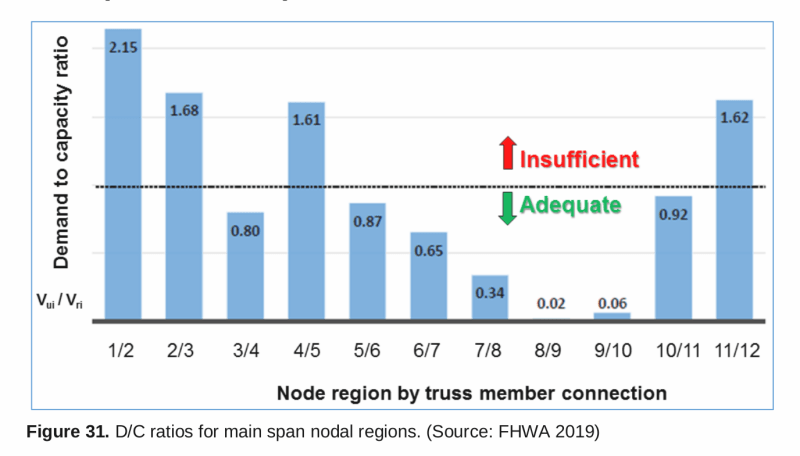
Pinning the hope in the soundness of the CJ won't hold any water because NTSB has already shown 11/12 has been massively underdesigned. NTSB would have by default assumed the Member 11/12 node constructed soundly without defect in ordedr to carry out the analysis.
F31_snrg0b.png
 
No PT bars were sheared at the construction joint, at least not until the portion of the deck was cut loose for examination.
 
Of all the errors, and there seem to be many, the worst was probably the decision to keep the road open during the "repair" efforts.
 
3DDave (Aerospace)3 Jun 20 01:05 SAYS:
"No PT bars were sheared at the construction joint, at least not until the portion of the deck was cut loose for examination."

That is correct 3DDave. That's because the PT bars were not connected to any other bars. They simply ended in 'space' embedded in concrete. Thus, they moved intact, together with the concrete surrounding them.
 
The lower bar lower attachment moved with the deck; the lower bar upper attachment moved with the canopy; between the two it tore the lower 1/3 of member 11 off and sliced through the reinforcing cage within 11. The concrete around the lower PT bar in 11 did not remain intact.
 
Wetlander said:
Of all the errors, and there seem to be many, the worst was probably the decision to keep the road open during the "repair" efforts.

Politics. If you shut the road then ABC is a failure. So they gambled they could fix it.

Rabbit12 said:
Wasn't there significant design errors made by FIGG? Where did admitting your wrong and accepting at least partial responsibility go?

No-one does that voluntarily. Everyone tries to offload as much responsibility as they can. Despite all our "codes of ethics" it's how engineering works when things don't work.
 
Status
Not open for further replies.

Part and Inventory Search

Sponsor

Back
Top