Eng-Tips is the largest engineering community on the Internet

Intelligent Work Forums for Engineering Professionals

  • Congratulations waross on being selected by the Eng-Tips community for having the most helpful posts in the forums last week. Way to Go!

Miami Pedestrian Bridge, Part XIV 78

Status
Not open for further replies.

JAE

Structural
Jun 27, 2000
15,433
US
A continuation of our discussion of this failure. Best to read the other threads first to avoid rehashing things already discussed.

Part I
thread815-436595

Part II
thread815-436699

Part III
thread815-436802

Part IV
thread815-436924

Part V
thread815-437029

Part VI
thread815-438451

Part VII
thread815-438966

Part VIII
thread815-440072

Part IX
thread815-451175

Part X
thread815-454618

Part XI
thread815-454998

Part XII
thread815-455746

Part XIII
thread815-457935


Replies continue below

Recommended for you

There are other concrete trusses (although they are rare) and they sometimes make sense. It is just that they have to be designed properly. Any material used can fail.
 
Hokie66 concluded that - "The design was fatally flawed, and hopefully will result in concrete trusses never seeing the light of day again."

Hokie, I believe the correct conclusion would be that, "concrete trusses with fatal flaws should never see the light of day again." Concrete trusses have been used endlessly in civil structures, and will continue to be so used.
 
I agree with Hokie66 that it’s the same crack. It simply opened further when it experienced serious loads. I don’t understand the distinction between 11 pushing and the deck pulling either. They’re one and the same.

I agree with saikee too that most of us dismiss cracks of that magnitude as “non structural”. I wouldn’t be prepared to condemn an engineer for dismissing initial cracking of that magnitude. We have the benefit of hindsight. They didn’t.


FortyYearsExperience,

There have been a few, but "endlessly" is stretching it. I have never seen one in person, and have more than forty years experience.
 
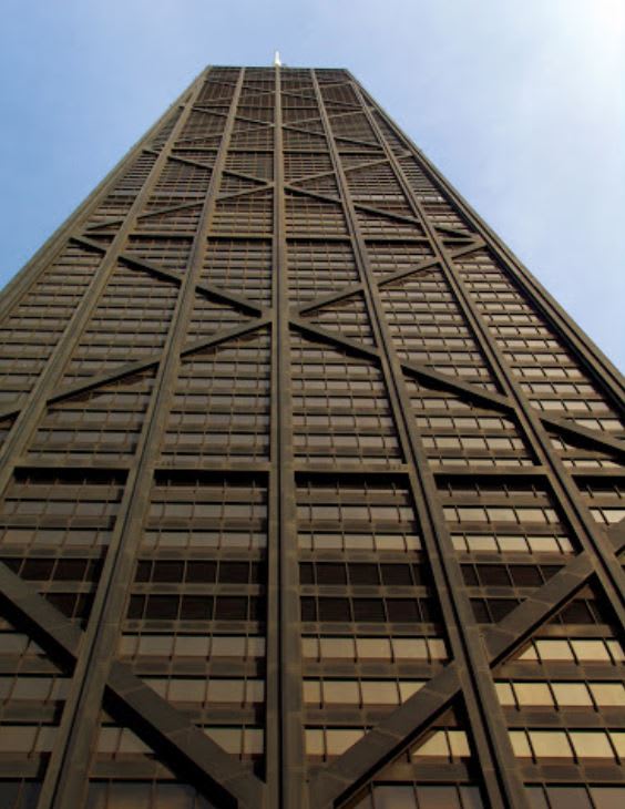
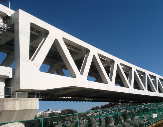
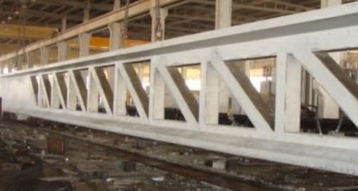
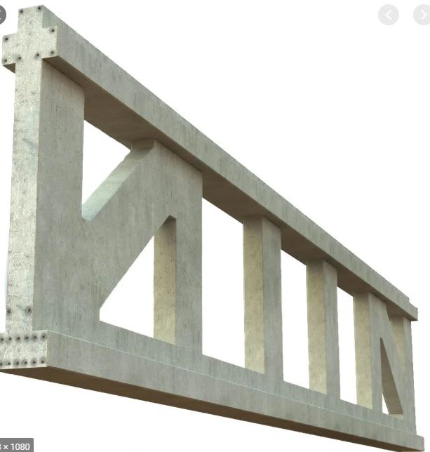
hokie66, I walk past this building every day. Ever been to Chicago? These concrete trusses can be found in just about every modern city. Sometimes they are concealed within the outer cladding of the building. Concrete trusses are well understood, and endlessly used.

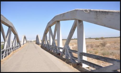
Concrete_Truss_pxetew.jpg
 
And no, no matter how many examples you find on the internet, I haven't seen any of them.

With the exception of the picture at the bottom left, which may or may not be a component in an intended bridge, I think the others are steel. But if you can provide some documentation otherwise, I am interested. Early on in these discussion of the Miami footbridge, I did some googling as you have done, and didn't find much. There was one example of a concrete truss bridge in Europe, maybe Germany, and it was very bulky in appearance.
 
The miami bridge was a concrete truss in the middle of two decks complete with a mismash and total mess of tubes, PT rods and a construction system which had cold joints all over the place. I'm sure those trusses, if they are actually concrete trusses, were made in a formwork laid on its side to avoid cold joints.

A pure concrete truss with decks resting on it may have been much better. It is likely the end re bar would have been tied back into the lower flange with something more than the equivalent of chicken wire or with PT rods running the full length of the truss properly capturing the forces from the lateral member.

It's not the truss per se which was at fault here, but the way the whole bottom deck, top canopy and intermediate asymmetrical struts were put together complete with all sorts of weak points. Member 11 just didn't have enough reinforcement to attach it to the bottom deck and blew out. Poor design.

Remember - More details = better answers
Also: If you get a response it's polite to respond to it.
 
LittleInch nailed it, especially his remarks about building concrete trusses on their sides.

A truss needs three things: compression, tension, and joints. Concrete is great in compression, useless in tension so requiring reinforcement, and tedious at best in joint design.

This was not just a truss, it was a truss/frame where the frame action was not addressed, and it had dissimilar chords without a rational way of getting the forces transferred between chords and webs. Differential volume change due to the construction sequence was the initiator of cracking. Altogether, an abject failure in design concept as well as execution. In addition, as a novel concept, it should have been tested. They had ample opportunity while it was still on the ground to load test it, probably using water bladders or sand bags as the test load.
 
saikee119 (Structural) 5 Jun 20 12:23 said:
What stopping Member 11 moving outward and way from the end of the structure was its strcutual connection with the deck.

My argument has long been that the connection of Member 11 with the deck was rendered irrelevant by the faulty design. Hence, Member 12 became the constraint preventing 11 from moving north. The meager rebar passing from the deck through 12 only serves to tear at the deck adding to the illusion of punch out. The lower PT rod becomes the mechanism of failure but is also the final snag holding the structure together until it tears out of 11. As I've stated previously, the lower PT bar initially held the structure together but once the tension was released, the structure relaxed and snagged. Adding load to the structure only exaggerated the deflection to its demise.

Importantly, the sleeve around the PT rod would limit the relative movement of 11 to the deck to approx. 1/2 inch. Further movement is allowed by the tearing of 11.

We have not seen images of the initial crack at 12 while the structure was still in the yard.

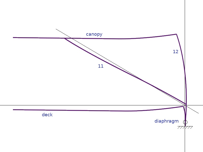
Consider the following diagrams:

Final_Effective_Structure.01_wbdcde.jpg

Bridge_Deflection_ynehlp.jpg


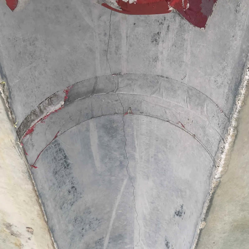
Also, the deck sag is greater along the center longitudinal axis than along the deck perimeter as is evidenced by the longitudinal crack along the deck underside in the drain cut-out.

Drain_cutout_Crack_wmp047.jpg

Bridge Factors Photo 71 – View of crack in cut-out for drain pipe under deck on 3/12/18 at 10:20
a.m. (Source: Munilla Construction Management, MCM)
 
Sym P. le (Mechanical),

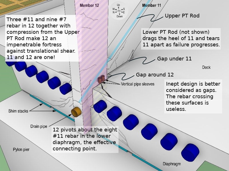
To me Member 12 wasn't an impenetrable fortress against the translation shear against Member 11. In fact it was almost like a lump of concrete attached to Member 11 that can be moved bodily with 11. That was the heart of the whole problem. If we temporarily ignore the contribution from the joint then structurally the only resistance of 12 against 11's horizontal shear is by bending its connection at its top with the canopy. Since 12 is about 18' high and the canopy is only 1' thick the rotational resistance at the canopy connection would be small even when there is a large displacement at the bottom of 12.

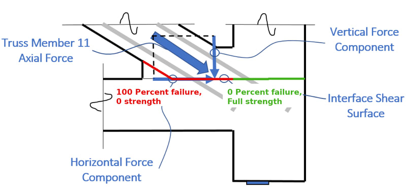
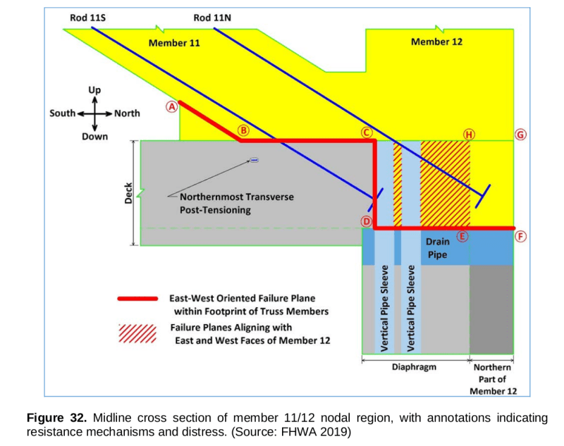
Your indication of the CJ sheared off along a horizontal plane, part red and part green, in your last sketch is not the path of the least resistance. The OSHA Fig. 58 to 70 inclusively show the shearing path was stepped. There was no concrete left on top of the 8" drain pipe in every one of the OSHA Figures. This substantiated after the CJ the failure plane had changed level to the top of the drain. The NTSB's version of the failure path is depicted by its Fig. 32 which is enclosed below.

F32_laqfj3.png


In a way it was the combination of the 4 No. of 4" pipe sleeves and one 8" drain pipe that broke the back of the camel. These embedded items apart from disallowing the necessary rebar to be placed, especially in the horizontal direction where it was needed most, they created a weak pocket for 11/12 to slide out once the reinforcement in the A-B-C part of the CJ had sheared off.

In NTSB Fig. 32 the part C-D would be in tension and in design offered zero resistance from concrete. If you scrape the barrel the concrete tensile resistance is around 0.5 to 2 N/mm2 which is insignificant. I believe there were only 4 No. #4 bars, availoable to resist tension, from the deck longitudinal reinforcement which again not much a fight against the huge shearing force from the Member 11.

The last defence against the shearing from diagonal 11 is the shearing capacity along part D-E-F plus the two vertical shearing faces indicated by hatched areas C-D-E-H-C, on each side of Member 12. Unfortunately the end of the deck has 12 No. of end anachors from the longitutinal strand tendons. They prevented any substantial rebar to be inserted into the hatched areas but the drawing B47 did show a couple of #4 bar. Part D-E-F has a decent amount of Vertical reinfrecment available to withstand the horozontal shear but unfortnately none of them failed in shear but by bonding accaording to the OSHA figures.
 
Thanks saikee, I'll post a response in a few days when I get home.
 
saikee, Thank-you again for your comments. I believe you have given an excellent summary of the issues encumbering the 11/12/"deck" node though you have understated the issue of the blue electrical conduit on either side of 12. These conduit are equivalent to an additional pipe sleeve on each side of 12. As such, I have considered these surfaces as contributing "zero" to the strength of the structure. As most agree, this node is the fundamental flaw in the structure.

In my stick diagram above, I attempted to show relative movements in the nodal region and also proposed an offset displacement of 11. My reasoning for this is that as 12 bows, the base of 11 tips upward, and as the bridge sags, the top of 11 tips downward. My depiction of the movement of the top of 12 and both the canopy and deck deflection is greatly exaggerated. A one inch relative motion between the deck and 11 would not result in the same movement elsewhere in the structure, rather, significantly less.

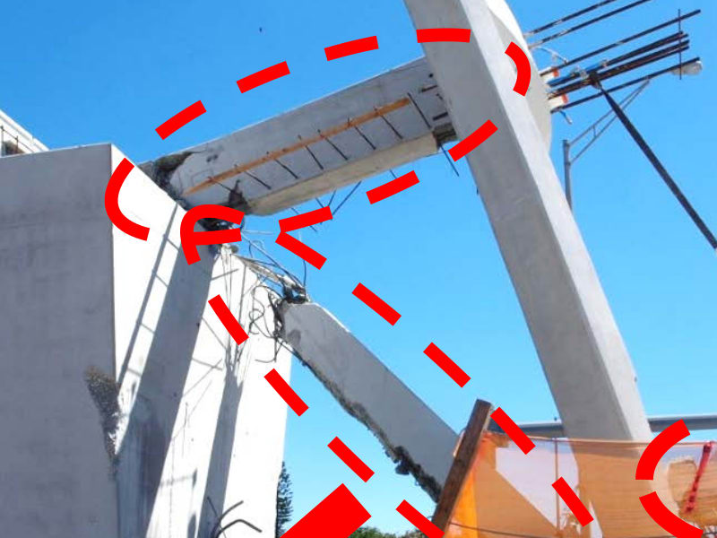
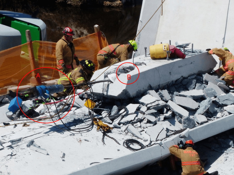
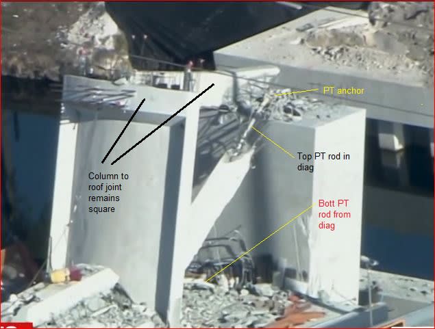
It seems to me that 11 is ill equipped to support the loads imposed on it both in its intended role and far less in its effective role. There is no question that the base of 11 is being torn apart. I suggest the following image, the significance of which has been overlooked, reveals that the failure of 11 was the "next step" in the collapse. The upper PT Rod has yielded at the failure point in 11 which indicates that its base was still firmly positioned in 12 as 11 sheared. The failure cascaded from that point as 11 pancaked while being guided along the lower PT Rod. Note that the lower PT Rod was free to extend out of the blister cap while the upper PT Rod was not.

Member_11_Mangled_Rebar_and_Upper_PT_Rod.03_cxvqzu.jpg

Evidence Testing and Results - Adrienne Lamm

canopy_blister.bLTBa6e_v9tqyr_d7h3wh.png

(epoxybot (Structural) 18 Mar 18 17:25)

As I reviewed the dash cam video, I noted that prior to 12 descending, the 10/11/canopy node dropped significantly while the deck had also rotated significantly. This suggests that the slab rotated off of the base of 12 and I've previously noted evidence of torsional failure in the diaphragm. The collapse of 11 would have hammered its own base, the 11/12 node and also the lower portion of 12, increasing the likelihood of the rebar being stripped clean.

The Shear Plane Fallacy as I posted only refutes the suggestion that surface treatment or lack thereof played any role in the collapse. Although weaker shear surfaces are identified, I do not find it plausible that the bulk of concrete and rebar in Member 12 was weaker than the distressed Member 11.

You rightfully raised the issue of language. It has me thinking that when the cracks first appeared as the shoring was removed the question that needed to be asked was "Is the structure fit for moving?" and this should have guided the inspection and review at that time. Figg was well aware that the node was critical and that the structure needed to survive a certain amount of jostling. As such, I think that the cracks were structural issues prior to the move.

(edit: removed blank space)
 
Sym P. le (Mechanical) said:
The upper PT Rod has yielded at the failure point in 11
FIUFailclipPTDiagPaint_yjogtw.jpg

i do not see an indication of failure of the upper PT rod in Member 11.
Is there a better image?
Thanks,
 
I'll post another one tomorrow, your image happens to be directly across the plane of failure. I had to remind myself that any "kink" in the PT Rods should not be there. The lower PT Rod, of course, was "kinked" at the slab from the structure snagging on it.
 
We now all know the 11/12 blew out from the deck. In this failure mode there is no need to stretch either PT rods in 11. There was also no force available to stretch them.

After failure the rigid PT rod, especially the bottom one, was severely bent so one can say the PT rods might have yielded but the yielding is consequential to and not contributory to the bridge failure.

It may difficult for non-structural engineers to appreciate but if the connection failed the first thing happened to a PT rod would be a total stress relaxation, or zero stress, due to a total loss in the anchorage. If a PT rod later yielded it could only be the bending stress from distorting an initially straight 45mm diameter rod. This is totally different from the unform post-tensions in the brdige design.
 
Status
Not open for further replies.

Part and Inventory Search

Sponsor

Back
Top