Eng-Tips is the largest engineering community on the Internet

Intelligent Work Forums for Engineering Professionals

  • Congratulations waross on being selected by the Eng-Tips community for having the most helpful posts in the forums last week. Way to Go!

Miami Pedestrian Bridge, Part XIV 78

Status
Not open for further replies.

JAE

Structural
Jun 27, 2000
15,433
US
A continuation of our discussion of this failure. Best to read the other threads first to avoid rehashing things already discussed.

Part I
thread815-436595

Part II
thread815-436699

Part III
thread815-436802

Part IV
thread815-436924

Part V
thread815-437029

Part VI
thread815-438451

Part VII
thread815-438966

Part VIII
thread815-440072

Part IX
thread815-451175

Part X
thread815-454618

Part XI
thread815-454998

Part XII
thread815-455746

Part XIII
thread815-457935


Replies continue below

Recommended for you

Hokie66, you say that, "We are talking about a concrete truss/frame here, not steel, cast iron, wrought iron, wood, or aluminum."

Hokie66, are you suggesting that because this truss is formed in concrete it is exempt from the requirement that EVERY truss/frame requires shear reinforcement at the nodes ?

Strut #11 has a load of 1,500,000 pounds pressing north. Can you identify any structure within the truss/frame that balances that force to prevent strut #11 from travelling north ?
 
You got it! The lower PT rod added shear force to the joint. Bad call by the EOR.
To your second point - as I recall, both PT rods were re-tensioned, alternating in 50 kip increments.
Kinda scarySo tragic to think of working on a joint having 1500 kips load which was less than 50 kips away from failing and causing the structure to collapse and then intentionally adding that last 50 kip load. And the damn thing killing so many.
(edit - I apologize for being so glib. That was grossly insensitive.)
 
While I am not old enough to remember the middle ages, I have been concerned about the interior nodes of this truss/frame structure where PT rods in tension terminate and must transfer connection forces to/from normally reinforced concrete having compressive forces using only the concrete in shear and with nominal if any dedicated containment reinforcing.
Were I to have designed the joints, there would have been generous weldments to firmly anchor PT forces and distribute bearing and rotational eccentricity forces to significant areas of concrete, with the steel providing shear transfers. And I would offer those weldments at nodes 1/2 and 11/12 for connection to your 25 square inches of tension reinforcing.
Together we could bring over 80 years to a project.


waross (Electrical) said:
I wonder if the drain, sleeves, and conduit were steel instead of plastic if it may have held together long enough for someone to condemn it without anyone dying.

I have thought about this too. I believe if the embedded items were strong enough to distribute the internal stress like a rebar the bridge could have lasted a lot longer. For that to happen the sleeves and pipes would have to be pretty thick and physically structural elements.

When the embedded sleeves, conduits and pipes are plastic with radically different in elasticity to the concrete and rebar the concrete surrounding them would be forced into higher stress due a reduction of area. The areas around these embedded services had formed hinges once the concrete had been crushed internally allowing the rebar a much higher degree of movements not permitted in a serviceable structure. The crushed concrete around the hinged areas would be loosened resulting the structural bonding of the concrete with rebar confined further high up in the elevation until the remaining available bonded length could no longer sustain the structure. In other word because of the embedded items wereable to nullify a section of the bonded length of the rebar the provided original development length had suddenly become inadequate.

In any design in reinforced concrete the fundamental assumption or requirement is there should be no slip between the concrete and the steel reinforcement and the two must have identical strain. Once this breaks down the design fails.

Like I mentioned previously all the rebar in the CJ were sheared off but all the vertical rebar in 12 were intact. None of them failed structurally. The concrete just couldn't grip the bars.
 
FortyYearsExperience (Structural)16 Jun 20 18:33 Vance Wiley (Structural) said:
I'm glad you agree that this node has no shear reinforcing at all.

Respectfully I beg to differ. No shear reinforcement is not the same as inadequate shear reinforcement provisions.

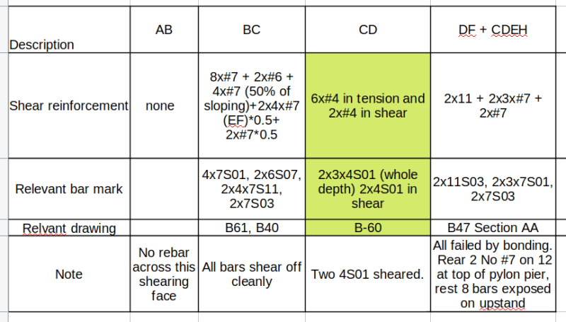
With reference to the NTSB Fig 32 posted most recently by Waross 15 Jun 20 23:06 I have established the rebar across the failed interface in the enclose table.

Shear_rebar_j63yqv.png


The area CD was in tension so strictly speaking not shear reinforcement but were available to stop the failure.

There were substantial vertical rebar of 2x#11 and 8x#7 across DF. They could have been able to resist the horizontal shear had the bars' development length not compromise by the crushed concrete around the embedded item. In the end these bars failed by bonding.

Apart from the sheared off reinforcement in the CJ (showed in construction drawing B61, B40) nearly all the rebar I quoted in above are visible from the OSHA report. An isometric cut out view prepared by NTSB final report as Fig 17, which I posted on 3 Jun 20 00:35, also shows the extent of the shear reinforcment available.
 
Hold on a minute - " at all" applies to some joints and some parts of joints but there was reinforcing in place that was intended to resist shear at the top of the deck in Node 1/2 and 11/12. Woefully inadequate and poorly detailed, but intended to resist shear. And some incidental reinforcing crossed shear planes in the sides of the blown out block below Node 11/12 but was also inadequate.
I can agree that, in the case of Node 11/12, the results suggest it may as well not have had any shear reinforcing "at all".
 
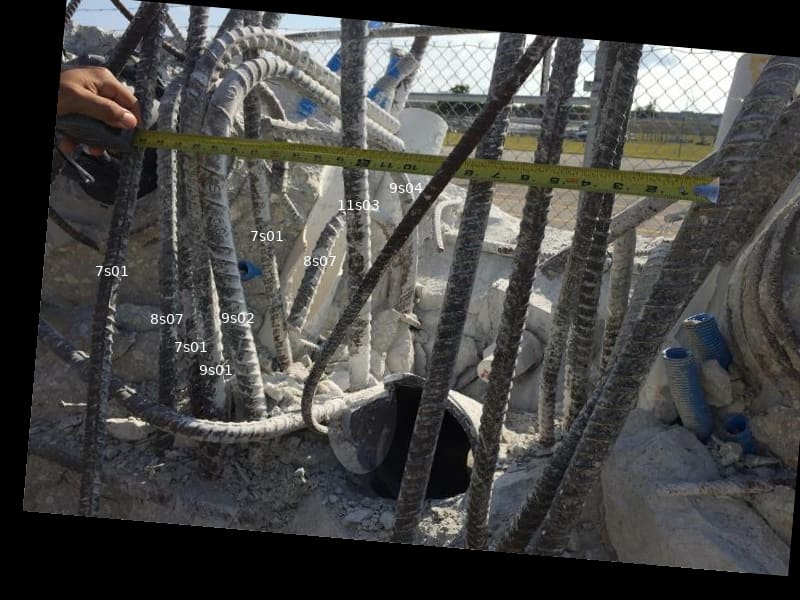
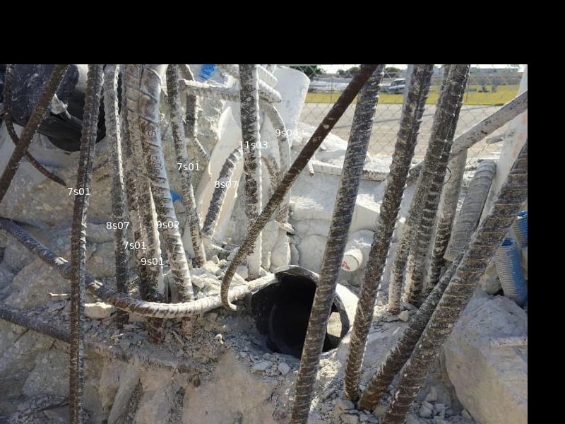
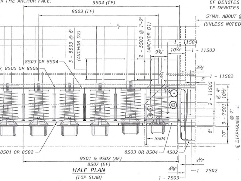
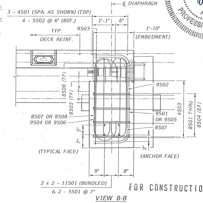
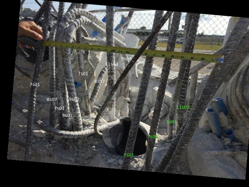
Rebar anomaly: on the east face of Member 12, 9s01, 9s02 and 9s04 are inside the 7s01 verticals. How's that for a twist??

Rebar_Anamoly_over_OSHA_pics.Fig_69.Pg99_utta6b.jpg


Rebar_Anamoly_over_OSHA_pics.Fig_70.Pg100_grazj4.jpg


B047_Deck_End_Diaphragm_Reinforcement_Type_II_or2zf8.jpg


B047_Deck_End_Diaphragm_Reinforcement_Type_II.02_zmvfyl.jpg
 
I wouldn't stake my forensic analysis business on regurgitating the NTSB report.
 
I can't imagine how nauseating it was to watch this happen. You've carefully placed the shims and then the structure heaves some more. Pushing, twisting, rotating, and leaning on one corner ... and you don't know why. Can you hear the record needle scratching as someone glibly says "Let's retension the PT bars, that'll work!" Do you think they were too dumb to sweat?

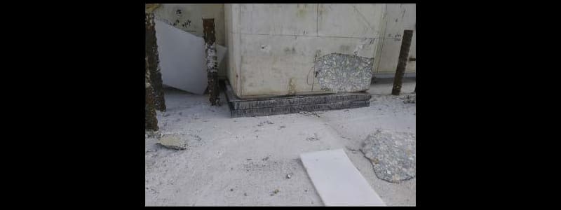
Chip_off_of_block_aswi3y.jpg
 
Sym P. le (Mechanical) said:
Rebar anomaly: on the east face of Member 12, 9s01, 9s02 and 9s04 are inside the 7s01 verticals. How's that for a twist??

The north face of rebar 9s01, 9s02 and 9s04 8s07 can be seen from every OSHA figure depicting the rear of the deck. Their east face can be seen on both south and west sides after 11/12 was blownout as evident in OSHA Fig 60 and 63, most recently posted on 2 Jun 20 01:24 here.

I believe these bars, forming a group of 7 on each side of 11/12, were shear reinforcement for the the longitudinal tendon forces applied to the 2'-3.785" thick deck against the rest of the 4'-3.875" deep edge beam. They were never intended to restrain 11/12 from blowing out.

During the course of bridge failure the two sets of 9s01, 9s02 and 8s07 were suddenly called upon to stop 11/12 from moving out. They could have failed by shearing off each steel cross sectional area if sufficient length of the rebar had been embedded above and below the shearing plane. As it happened the shearing plane was at the level of 8" PVC drain pipe and evidently above this level the embedded length of 9s01, 9s02 and 8s07 were insufficient (because a failure plane was never envisaged there) so the concrete broke off instead of steel bars sheared off. Structiurally speaking the force needed to break the concrete bond off from the rebar here was less than that required to shear off the 4 number of #9 and 4 number of #8 steel bars. The bond had also been severely compromised by the close proximity to the 4 No. of the 4" vertical plastic sleeves.

To me there was no anomaly of 9s01, 9s02 and 8s07. They were just bars designed for other purpose inside the connection that the blown-out surface interfering with. Approximately a length of 45 times the diameter of a rebar is needed to be fully embedded in sound concrete to allow the steel stress to be fully developed. By inspection 9s01 and 9s02 do not have 45*1.125 = 50" above the failure surface.
 
The rebar in Member 12 is indeed asymmetrical, and were it not for the catastrophic failure it wouldn't be much of a big deal. Others noted some time ago that the distress revealed in the structure was also asymmetrical. The 11s03 in the SW corner of Member 12 is also misplaced and asymmetrical to the placement of its equivalent in the SE corner.

This speaks not only to the level of care taken during construction, but also to the attention to detail taken by those who are appointed to review this sorry affair and did not point this out. This is not a figment of my imagination. I am not interested in comparing reality to the theoretical performance expectations of mythical structures.

Rebar_Anamoly_over_OSHA_pics.Fig_69.Pg99.02_i6fyb6.jpg


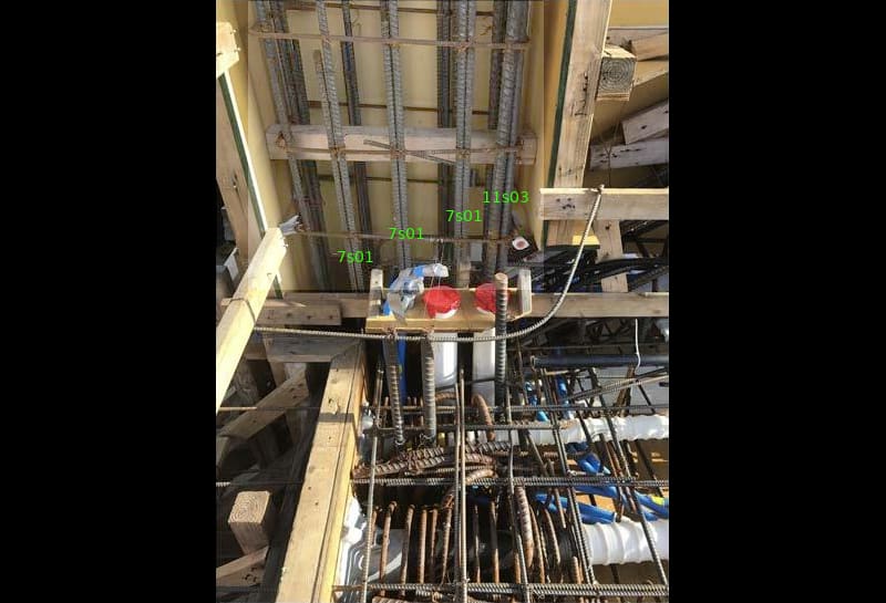
MCM_Page_46_Fig_30.labeled_qresji.jpg
 
Sym P. le (Mechanical)17 Jun 20 18:10 said:
(bottom photo)
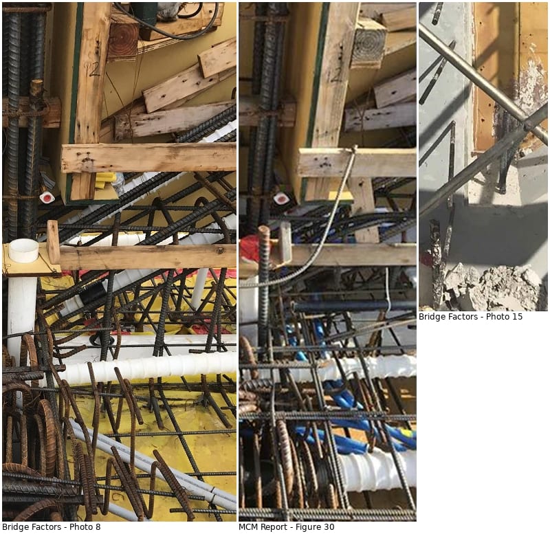
Thanks for calling our attention to this photo. It looks like Grand Central Station in the deck below 11's position.
I see curvy black things that weave around the vertical 2by. They look like rebar but are blacker. Also all the blue conduit running side by side seem to leave no room for concrete between them. And whats the smooth black pipe hung with ziptie under the deck floor? I'm mystified.

SF Charlie
Eng-Tips.com Forum Policies
 
What would be the ultimate strength of member 11 under compression.
Would the 1,500,000 lbs plus the added tension of the PT bars be close to the failure point of # 11 under compression?
Thanks.

Bill
--------------------
"Why not the best?"
Jimmy Carter
 
SFCharlie, I'm not sure what you're looking at.

waross, I believe this has been covered with the conclusion being that it is close. But that would be a theoretical limit below which significant confidence could be placed that failure would not occur. In this situation, the design intentions were not met so the additional question is what parameters should guide the calculations.
 
Sym P. le (Mechanical) said:
The rebar in Member 12 is indeed asymmetrical, and were it not for the catastrophic failure it wouldn't be much of a big deal. Others noted some time ago that the distress revealed in the structure was also asymmetrical. The 11s03 in the SW corner of Member 12 is also misplaced and asymmetrical to the placement of its equivalent in the SE corner.

This speaks not only to the level of care taken during construction, but also to the attention to detail taken by those who are appointed to review this sorry affair and did not point this out. This is not a figment of my imagination. I am not interested in comparing reality to the theoretical performance expectations of mythical structures.

I wouldn't be too harsh on the quality of workmanship here as it wasn't a contributory factor to the collapse.

From the available photo the rebar of 12 were seen in reasonable format and position before the pour. By comparing them with the heavily distorted final positions after the failure can be misleading and even dangerous because we do not have a 3D image showing the exact embedded position of every bar. The important consideration should be had any bar been omitted, changed size or cast wrongly?

Fixing reinforcement is not an exact science. No matter how clever is the designer's concept we still have to rely on mostly emi-skilled labourers to execute the works of fixing the bars and erecting the formwork. The accuracy they use is about an quarter of an inch if we get lucky.

The main failing of this bridge is the designer has not thought of the congestion from the embedded sleeves, ducts and pipes resulting omission of vital reinforcement to link the 11/12 solidly with the deck. The drawings show a symmetrical design, for drawing office economy, but the site work show a few odd bars lapped at slightly different locations asymmetrically for avoiding services is a fact of life in every reinforced concrete structure.


Thanks Sym P. le


Bill
--------------------
"Why not the best?"
Jimmy Carter
 
SFCharlie (Computer) 17 Jun 20 18:45 said:
I see curvy black things that weave around the vertical 2by. They look like rebar but are blacker. Also all the blue conduit running side by side seem to leave no room for concrete between them. And whats the smooth black pipe hung with ziptie under the deck floor? I'm mystified.

I think the curvy black things are grout bleed tubes for the PT rods. The smooth black pipe looks like a screed rail to aid pouring the deck.

Is there any redeeming structural value in the Member 11 PT rods by grouting them had the structure been successfully positioned?

Several photos of the work in progress. The top mat of deck rebar has not been installed in the first photo (Photo 8). The final installation of the grout bleed tubes extend upwards in the filet (Photo 15). They probably required a hole to be drilled in the form work (Fig. 30)

Lower_Member_11_Rebar_etc_le27th.jpg
 
I would grout the smooth PT rods to protect them and the concrete sections from the elements. And the PT code requires that tendons be grouted, of course. So grouting would express a semblance of conformity and care.
The relaxed rods would have no structural contribution in a compression member. Actually, as the compressiomn members like M11 "creep" and shorten under long term compressive loads, the rod will push on the closure at the top, and probably should have a void provided to maintain a cap or plug at the top.
 
waross (Electrical) said:
What would be the ultimate strength of member 11 under compression.
Would the 1,500,000 lbs plus the added tension of the PT bars be close to the failure point of # 11 under compression?

I try to answer your question as I think you could be barking on the wrong tree by thinking the compressive stress played a significant role in this bridge. Speaking from a civil/structural background I would say a reinforced concrete structure rarely fails in compression.

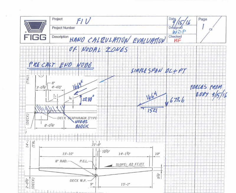
Figg_design_forces_in_11_uotyed.png

Above is the Figg's calc submitted to NTSB. Most of it was computer print out but some hand calculations were added as sanity check. The design force in 11 was 1664k.

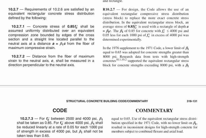
ACI318_on_compression_xpy0hq.png

The design compressive stress in concrete can vary slightly with design codes but the main stream ACI318 prescribes 0.85f'c for 4000psi concrete and reduce 0.05 per 1000psi above 4000psi. Thus the charcateristic compressive stress is 0.75f'c fora specified strength 6000psi (see construction drawing B38). 11 has a dimension of 2'-0" by 1'-9" so the compression capcity from the concrete alone should be at least 0.75x6000x21x24/1000 = 2268k or 1012 ton without even consider the contribution from the compression reinfrcement. Since the bridge weighs 950 ton (construction drawing B37) so compression isn't a problem.

After the collapse NTSB cut 8 cores out of the bridge structure. The three cores from the deck have recorded failure stresses between 8580 to 10770 psi which are comfortably above the specified strength of 6000 psi. It is normal for the site concrete to be higher than the specifed strength. If a contractor supplies a poorer mix design that fails below the specified strength he could be asked to demolish the bridge before it leave the casting yard. Due to the standard deviation in the concrete quality control there is usually a modest safety factor available but never included in the design.

Therefore the concrete compression in 11 will not be a significant contributor to the failed bridge both in theory and practise.
 
Status
Not open for further replies.

Part and Inventory Search

Sponsor

Back
Top