Continue to Site

Eng-Tips is the largest engineering community on the Internet

Intelligent Work Forums for Engineering Professionals

  • Congratulations GregLocock on being selected by the Eng-Tips community for having the most helpful posts in the forums last week. Way to Go!

Miami Pedestrian Bridge, Part XV 15

Status
Not open for further replies.

Sym P. le

Mechanical
Jul 9, 2018
1,081
Please allow me to continue the previous thread (Miami Pedestrian Bridge, Part XIV) as the prior is getting unwieldy.

For those who have lost track of the discussion, my summary is that we have most recently moved into a discussion of the progression of nodal region deterioration of members 11, 12 and the deck as it pertains to the physical placement of the structure in its permanent location, then detensioning of PT rods in member 11, and then prior to retensioning of same. Epoxybot was able to connect the timeline of texts sent by Kevin Hanson inquiring of necessary supplies prior to detensioning with the timestamp on photos indicating significant deterioration prior to detensioning. I was reviewing documentation trying to narrow down on this timeline to confirm this critical detail with the implication that analysis contributed to the NTSB review has conflated events and attributed them to post-detensioning occurrences thus leading further analysis astray.

I have also posted what I consider evidence of compression failure of member 11 as the leading event of the collapse immediately after completion of retensioning PT rods in member 11. This includes questionable reinforcing design and deformation patterns in exposed rebar post-collapse.

To forward my own hypothesis, it is that two failure mechanisms were at play, one was the nodal region degeneration, and the second was the member 11 degeneration as it came into the nodal region. Although they played into each other, the weaker nodal region allowed the deck to detach from the node but the structure was able to rely on the connection of the diaphragm with the repurposed member 12 (i.e. a connection not including the deck). Meanwhile, the demand on the flawed member 11 grew and the structure collapsed when 11 failed just above the node.

P.S. With this new and more nuanced timeline, it allows the identification of three significant events to member 11:

1 - Overloading upon removal of shoring followed by release when mounted on transporters,
2 - Overloading upon setting on piers followed by release with detensioning,
3 - Overloading upon retensioning of PT rods followed by collapse.​

 
Replies continue below

Recommended for you

"It will be interesting when the report on the collapse is completed, how many of the comments in this thread 'ring true'."

A quote from this forum, from nearly 2 years ago...

Rather than think climate change and the corona virus as science, think of it as the wrath of God. Feel any better?

-Dik
 
Sym P.Le said:
They are distracted with their preconceptions and that is why their explanations are continually oddball and contradictory.

By carrying on with their chosen path, the educational aspect of this disaster their review is completely lost. The discussion about cracks is a case in point.

Well at one point you were posting heavily in agreement with their final analysis, and I have yet to see anything that warrants your arrogance. I don't really understand what your motivation is, to be honest. The path of their analysis leads to a pretty clear conclusion, while yours, to me, does not.

I don't know if it's the truth or not, as I don't know you personally- but your posts come across as determined to prove that the NTSB could not possibly be right, and that the answer to the question about what caused this bridge to collapse is, quote, 'patently obvious'. I submit that if the answer was as plainly obvious as you say, we wouldn't still be talking about it 15 (!) threads and just shy of three years later.
 
I thought the NTSB report was a little lacking, too. If "They straight up say that is their sole objective in their report." was the total objective they may have achieved that, albeit a little 'light' from my perspective. I don't not recall what their sole objective was.

Rather than think climate change and the corona virus as science, think of it as the wrath of God. Feel any better?

-Dik
 
Reading through the interviews with the FIGG folks the NTSB seemed to focus a lot on the re-stressing of the node. A lot of the answers talk about how the bridge was supported after it was cast and before it was moved. Was the support after it was cast identical to the support over the roadway?
 
I doubt that I've posted anything heavily in agreement with the NTSB final analysis. They apportioned plenty of blame to go around, which I have to agree with. Even at that, if an engineer can't spec a column or column rebar properly, can the construction crew bear much responsibility for building that design?

Aside from the usual concern of human tragedy, my attention was piqued when reports said that crews were restressing Post Tensioning elements at the time of collapse, and that sounded a little off. It sounded more ridiculous when I realized they were adding compression to a critical compression element (that by some estimation looked quite thin). I have never seen the idea of 11/12 sliding off the north end as a reasonable explanation, nor can I believe that a little bit of air chisel to a patch of interface less than four foot square, or "more rebar than can fit" should be an adequate solution to keep 900 tons from collapsing.

My curiosity kept drawing me back until I happened to make a connection (which I posted in Part XIV, 26 Nov 20 01:39) precisely locating the stub of Member 11 to the formwork/rebar photos and that's when I finally realized what I was looking for. That this explanation (compression failure) was hanging in plain sight for all these years does not lessen its validity. We all missed it even though we were all looking at the same deficient design drawings.

I realize that many are tired of me pointing to alternate explanations for what the photos show, but the pieces that I've put together add up. Unfortunately they are hit and miss with dead end theories and spread out over fourteen pages but the conclusion is unmistakable. The NTSB did not examine the adequacy of Member 11 because they already had their answer.

/end of rant, sorry
 
The deck is sagging and moving south relative to 11/12 thus causing the diaphragm to twist. The heel of 11 was not capable of punching out the slab thus it is a very weak argument that somehow the toe of 11 punched out the base of 12. The NTSB essentially posits that the toothpick (11) when pressed against the 2x4 (12) caused the 2x4 to fail which in turn caused the tip of the toothpick to break off.

Does anyone have a take on how much 11 would compress longitudinally at its critical load (Edit: or should I say the critical load of the unreinforced concrete since the rebar was free to pop out)?

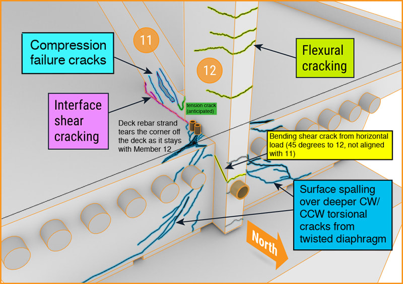
The interface shear cracks (below, fuchsia) become vertical, encompassing 12.

FIXED IT
Crack_Discussion_kdhdsx.jpg

NTSB's Executive Summary (from the investigation web site)
 
NTSB Final Accident Report HAR1902, under Executive Summary, Safety Issues page xiv, "The investigation of the collapse of the FIU pedestrian bridge focused on the performance of the northernmost nodal region (11/12 node) of the 174-foot-long main span. The failure of this nodal region was the triggering event for the bridge collapse.

It's rather difficult to move away from that if you're focused on finding that conclusion.
 

concur... I think you've summed it up very nicely. The beginning of Part II is a great read...

Rather than think climate change and the corona virus as science, think of it as the wrath of God. Feel any better?

-Dik
 
Rabbit12 (Structural) said:
Was the support after it was cast identical to the support over the roadway?

Two primary differences to the support over the roadway: 1. the formwork provided continuous support under the diaphragms as opposed to the pads supporting the structure on the piers when over the road, 2. The structure slopes downhill to the south whereas it may have been cast horizontally level with a tilt built into 1 and 12 and the diaphragm ends to accommodate the sloped installation (at least that's my take on the drawings)

I think the interview questioning was aimed at examining the dependability of the first scenario.
 
For the slight tilt, I don't think it would make any difference.

Rather than think climate change and the corona virus as science, think of it as the wrath of God. Feel any better?

-Dik
 
Sym P. Le said:
"The investigation of the collapse of the FIU pedestrian bridge focused on the performance of the northernmost nodal region (11/12 node)

Yeah you keep saying that... but the north end compression cracks in member 11, which you keep talking about as the 'real' root cause, are shown in all the diagrams in the NTSB report that outline the failure.

Your whole position on the NTSBs perceived incompetence is that they evaluated the joint between the deck and the node and completely ignored the concrete three inches away in member 11. Their documents don't indicate that, at all. You seem determined to find any reason why they're wrong and you're right.
 
If the NTSB failed to recognize compression failure in a concrete column, that would be a big problem.
 
Right... and they didn't fail to recognize it. This is why your point isn't clear.
 
Can you point me to the documents where they identified member 11 failing in compression.
 
Sym P. Le said:
Can you point me to the documents where they identified member 11 failing in compression.

It's very clearly stated in the probable cause defined in the full report. You can google it if you want.

Their conclusion is load calculation in the 11/12 nodal region - which includes the section of member 11 you claim they ignored - AND the interface to the deck. As in, they are identified as separate calculations which both contain errors.
 
I didn't think they had identified the actual failure member... have to take a gander again...

Rather than think climate change and the corona virus as science, think of it as the wrath of God. Feel any better?

-Dik
 
SwinnyGG, You are correct that I have erred in the use of the term "nodal region" as it clearly was a term coined by the review to include the lowest portion of Member 11. This, however, is an exercise in semantics as the review then narrowly focuses on the cold joint interface and attributes all of the visible deterioration to a failure at that surface. In turn, their calculations are narrowly focused on that surface.

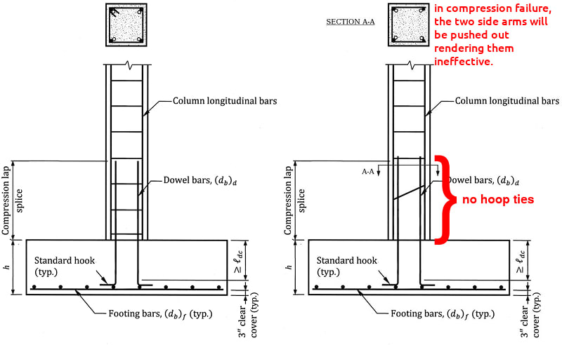
What I am pointing to is a design flaw which I consider part of Member 11. I differentiate from the nodal block based on the rebar design which includes a cage that extends only about 8" above the deck or the height of the filet beneath 11. In Part XIV, I posted a sarcastic sketch illustrating the problem, and I will post a comparison here. No one in their right mind would consider the detail on the right side, yet this is essentially the detail used at the base of Member 11.

**** Note: Member 11 does not have any corner rebar ****

Compression_failure_comparison_o5lfon.jpg

sketch from STRUCTURE magazine


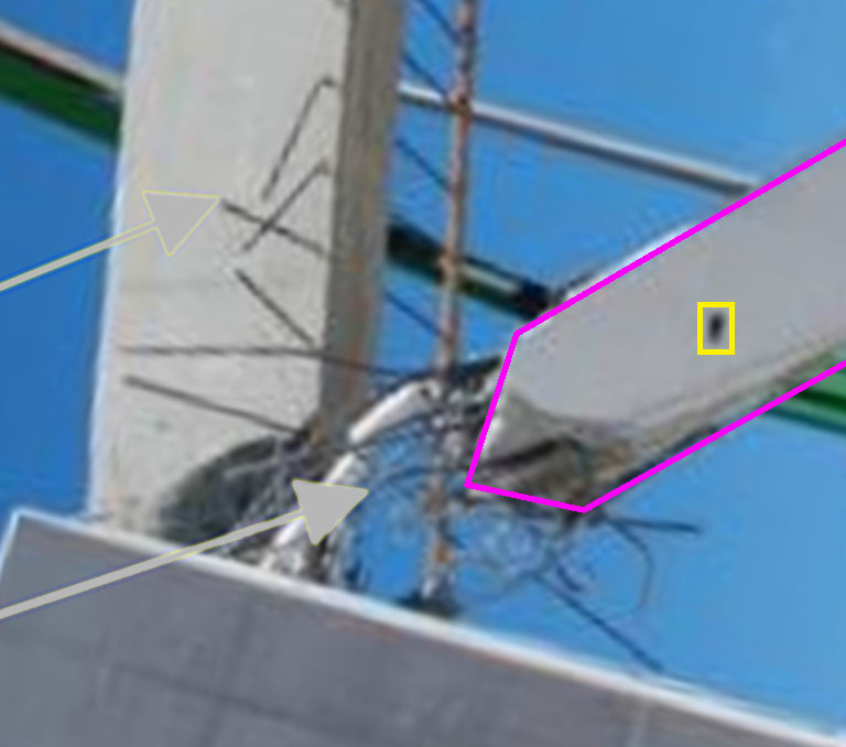
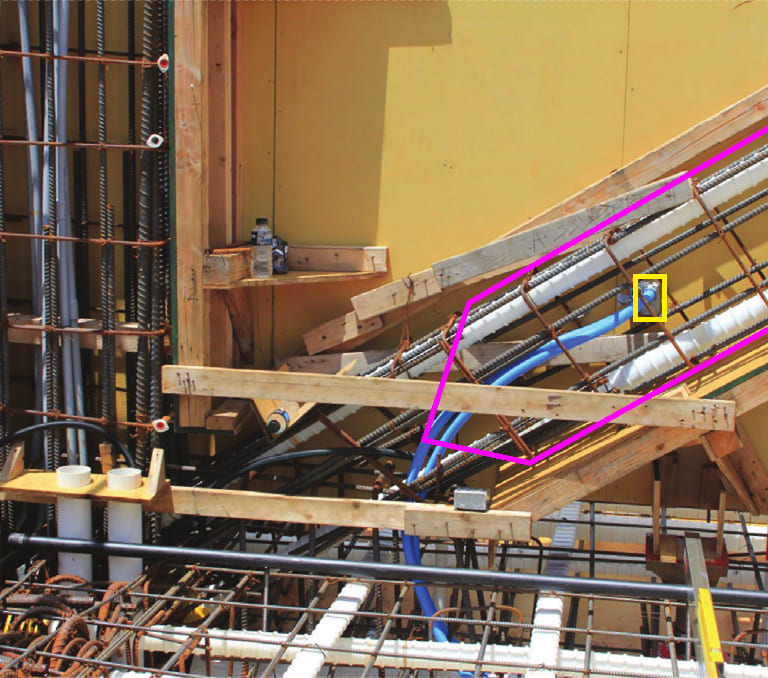
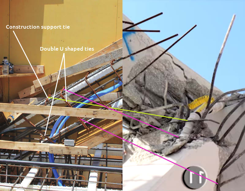
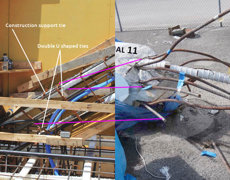
The precise location of the failure in Member 11 is easily seen in the following photos. Note that the skewed U shaped tie (called for in the design) is doubled and the lowest full hoop tie is substituted with double U shaped ties. Unfortunately, Member 11 needs to carry 450 xxx tons through to the deck/diaphragm but the design is clearly inadequate. Calculations are not required and this clearly is not part of any design node, it is the bottom of Member 11 above the node.

Electrical_Outlet.04.02_jiiydw.jpg


Electrical_Outlet.04_cvqhny.jpg


Compare_li4c1k.jpg


Compare.2_dqhc9j.jpg
 
Sym Pe said:
No one in their right mind would consider the detail on the right side, yet this is essentially the detail used at the base of Member 11.

They used overlapping U bars didn’t they? Not great, but hardly analogous to a single U that can easily open.
 
As seen in the rebar drawing photo, they did use overlapping U bars. I did the sketch based off the design drawing before I understood as built photos.

It's hard to make allowances for flaky designs with the results produced. I can see in the bottom photo that the two east side longitudinal rebars were sprung free along with the east top face longitudinal rebar. Combined with excessive spacing, this should be seen as something not to do. The substitution for the lowest full hoop seemed to work.
 
Status
Not open for further replies.

Part and Inventory Search

Sponsor