Eng-Tips is the largest engineering community on the Internet

Intelligent Work Forums for Engineering Professionals

  • Congratulations waross on being selected by the Tek-Tips community for having the most helpful posts in the forums last week. Way to Go!

Miami Pedestrian Bridge, Part XV 15

Status
Not open for further replies.

Sym P. le

Mechanical
Jul 9, 2018
1,032
0
36
CA
Please allow me to continue the previous thread (Miami Pedestrian Bridge, Part XIV) as the prior is getting unwieldy.

For those who have lost track of the discussion, my summary is that we have most recently moved into a discussion of the progression of nodal region deterioration of members 11, 12 and the deck as it pertains to the physical placement of the structure in its permanent location, then detensioning of PT rods in member 11, and then prior to retensioning of same. Epoxybot was able to connect the timeline of texts sent by Kevin Hanson inquiring of necessary supplies prior to detensioning with the timestamp on photos indicating significant deterioration prior to detensioning. I was reviewing documentation trying to narrow down on this timeline to confirm this critical detail with the implication that analysis contributed to the NTSB review has conflated events and attributed them to post-detensioning occurrences thus leading further analysis astray.

I have also posted what I consider evidence of compression failure of member 11 as the leading event of the collapse immediately after completion of retensioning PT rods in member 11. This includes questionable reinforcing design and deformation patterns in exposed rebar post-collapse.

To forward my own hypothesis, it is that two failure mechanisms were at play, one was the nodal region degeneration, and the second was the member 11 degeneration as it came into the nodal region. Although they played into each other, the weaker nodal region allowed the deck to detach from the node but the structure was able to rely on the connection of the diaphragm with the repurposed member 12 (i.e. a connection not including the deck). Meanwhile, the demand on the flawed member 11 grew and the structure collapsed when 11 failed just above the node.

P.S. With this new and more nuanced timeline, it allows the identification of three significant events to member 11:

1 - Overloading upon removal of shoring followed by release when mounted on transporters,
2 - Overloading upon setting on piers followed by release with detensioning,
3 - Overloading upon retensioning of PT rods followed by collapse.​

 
Replies continue below

Recommended for you

The U bars would have ripped open freeing the longitudinal bars during the collapse - yes?. Or are you saying that confinement failure of the longitudinal bars was already underway?
 
The confinement failure was already underway. When the PT rods were fully retensioned, 11 failed in compression, springing the shorter exposed bar free while the rest, still fixed in the deck/12 are deformed.


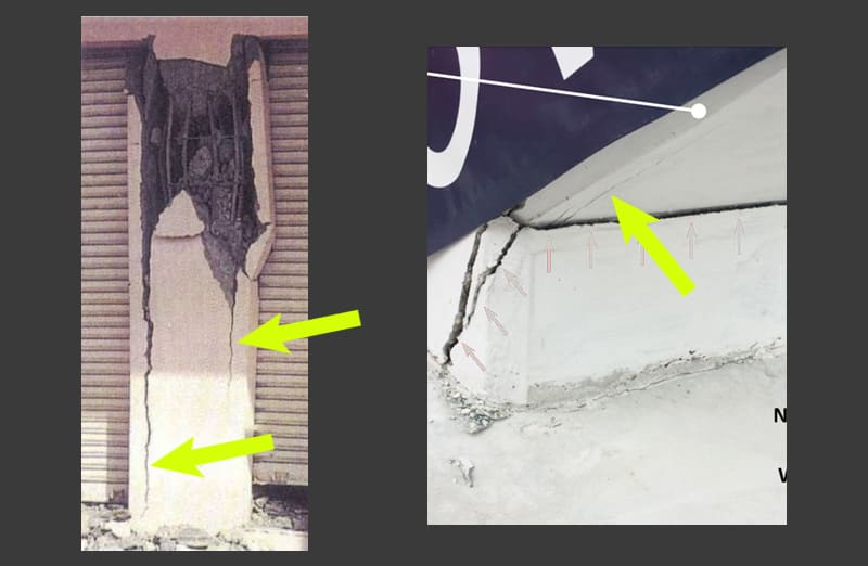
For further thought.
Splitting_Crack.02_tdc5tc.jpg

left photo from gharpedia.com right photo from Alexis Molina prior to detensioning.
 
The NTSB did not core the truss members for evaluation. Although all other testing confirmed the adequacy of the concrete, I felt that they were presumptuous in skipping that opportunity.
 
If 11 failing in compression was the instigator of the failure, the base of 12 would not have been driven north out of the deck, 12 would have failed in bending somewhere midspan, instead of remaining mostly whole as it was post collapse.

I don't believe that the configuration of the various components as they appeared after the collapse supports your theory.

The photo you've posted above makes it very clear that the node has already migrated north when that photo was taken; member 11 is cracked, but the totality of information is not consistent with a lack of capacity in the last 24" of member 11 being a singular cause for the collapse.

I honestly find it pretty ridiculous that you're leaning into this so hard. The photos don't lie, and they disagree with you.
 
The cracks on the east and west faces could be complicated by the interface movement but I can't see the underside longitudinal cracking being affected by that movement at all. Another complication when making comparisons is that member 11 doesn't have any rebar in the corners whereas most examples, if not all, do.
 
The root crack at the base of 11 which runs east-west, and is open by 1/4" or more, cannot open unless the base of 11 has moved north relative to the deck. Cracks can only open if there is localized crushing (i.e. material is removed) or if there is relative movement between components on opposite sides of the cracks.

All the other cracks on 12, in the deck, between the deck and the node areas, are all consistent with the 11/12 node moving north. They are not consistent with compression failure in 11 being the sole trigger.

The video of the collapse also very clearly shows that at the moment of collapse, debris was blown north from the north side of the 11/12/deck joint, and that the canopy hinged at or near the 10/11 node. None of that is consistent with a compression failure in 11 until after the node has already detached, the collapse is in progress, and 11 is compressed dynamically by the movement of the other members.

Was 11 underdesigned? Without any doubt. But you seem to be ignoring everything else which was underdesigned.
 
SwinnyGG,
You cannot say definitely that the member 11/12 node moved north. There was relative movement between those members and the deck, but you are discounting the shortening of the deck. There was a lot of PT in that deck, which combined with drying shrinkage meant the deck had to shorten, and the frame members tried to restrain that shortening. The crack had initiated even before the frame was moved to the site.
 
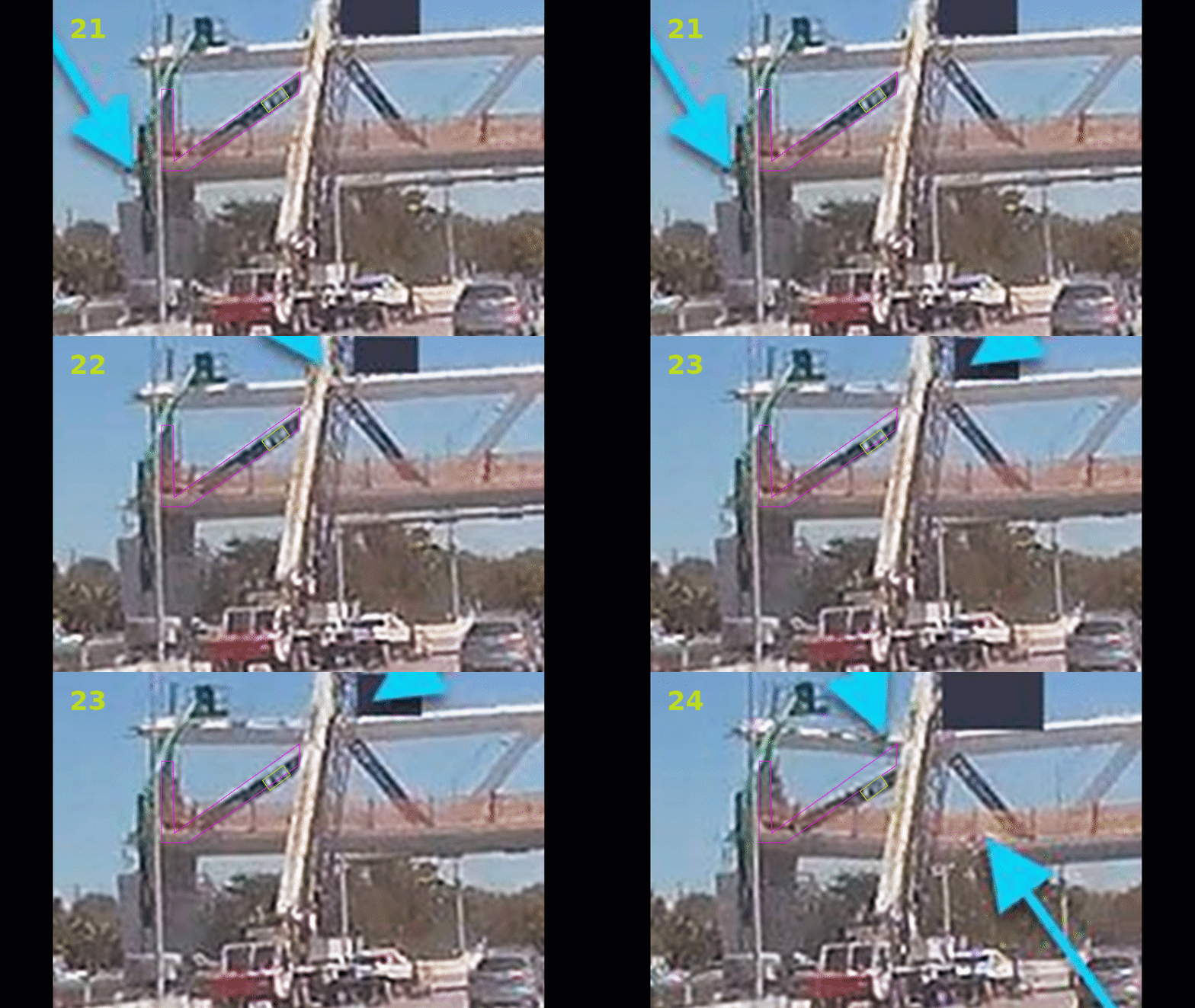
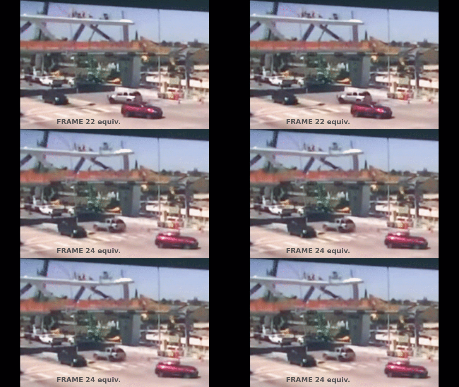
From the Security Video Factual Report (item 106 from HWY18MH009 Docket), the GoPro frames 21 to 24 offer the best indication of the events immediately after Member 11 retensioning was completed. Also the FDOT frames offer support. In both cases I've tuned up the colours to offer more clarity.

The GoPro frames are aligned vertically at the top of the west end of the pier and horizontally at the southeast corner of Member 12. This gives us the best opportunity to observe relative movement of concern. The scale has some issues since the camera platform was moving (increasing frames magnify the subject vertically and horizontally) but over 4 frames, this just needs to be taken as advisement. I've simply magnified the images for processing but have not rotated them or manipulated them otherwise because the vague detail deteriorates quickly.

Frame 22 gives the first indication of collapse and, of interest, in frames 22 and 23, Member 12 does not move from its base. In frame 24, Member 12 shows severe bending which I take to indicate that it's still firmly attached at its re-purposed base, it's connection with the diaphragm. Of further interest is the vertical decent of the banner graphic (or the 10/11 node at the canopy). These two observations offer proof that Member 11 is being reduced. From a fixed point, any other point along a hypotenuse of length 'c' that is following a downward vertical trajectory sees c1 > c2 > c3 etc. So we have all the proof we need to show Member 11 failed in compression.

To further follow my theory, Member 11 is also pushing out to the east and as it gives way, the structure descends. The canopy and slab both show indications of failure in frame 23, the canopy on its upper surface and the deck on its lower surface. Both are fully fractured in frame 24. Through these frames, Member 12 is held in its vertical alignment by the rotational trajectory of the north south portion of the structure.

As Member 12 is held in place and the slab starts to descend at the 9/10 node, the slab rotates the diaphragm off of the base of 12. Torsional failure is super efficient at turning concrete into small chunks, thus explaining the gaping void and surface spalling that wrapped around the base of the diaphragm.

And before I forget, the big blue arrow in frame 21 which the NTSB identified as a concrete blowout can plainly be seen as the bundle of pull cord or flagging that is hanging off of the corner of the deck. All of this has been covered before but I've reordered it to make my point.

Thanks.

Take_2_nhmoxr.gif


untitled_nt0dhe.gif
 
Where's the breakage in member 12 where that video shows it bending, because there is no way it could bend that much without being damaged. The failure damage in member 12 is at the deck joint end, not in the middle. If you consider that it's a video artifact and that member 12 was actually relatively straight the bottom was moving north.

Also, I see a funny step artifact in the deck line below or just a little to the left of member 12 in those 2 frames.

Personally, I have yet to see picture or video evidence that proves what exactly happened either way, other than it seems obvious the failure started at the bottom of that 11-12 node.
 
Barrel distortion in the lens or rolling shutter effect from the video camera do not negate the fact that the base of Member 12 had not gone anywhere significant by frame 24. They still support the fact equally as strong as an exquisite video system. You're suggesting that a propeller is not attached to an airplane if it looks weird in a video.
 
Sadly. the traffic lights hide the east edge of the deck and the crane hides the top of 11, but it is clear that the north end of 11 descends while the deck does not. The bottom of 11 must be damaged while 12 manages to remain.
PS the rolling shutter effect can be seen in 11 horizontal with the "bend" in 12.

SF Charlie
Eng-Tips.com Forum Policies
 
You completely ignored the question I asked and instead posted some stupid comment about a propeller and airplane. How about you answer how 12 could bend like that and yet not have any damage where it bent?
 
LionelHutz (Electrical)20 Feb 21 02:21]...how 12 could bend like that and yet not have any damage where it bent?
It did not bend. What appears to be a bend is the the camera recorded the top half (of the frame) later than the bottom half. Please note that this camera artifact extends all the way horizontally across the frame.
Thanks

SF Charlie
Eng-Tips.com Forum Policies
 
In frame 24, Member 12 shows severe bending which I take to indicate that it's still firmly attached at its re-purposed base, it's connection with the diaphragm.

It not actually bending is why I don't agree with this. The angle of the canopy in frame 24 and the fact 12 stayed attached to the canopy after the collapse together strongly suggest the bottom of 12 was moving north, not still attached.
 
Sym P.le said:
long post

11 is not translating purely vertically- it is rotation about the end attached to the node, along with the node.

Your own markup shows this clearly. The displacement relative to the north end is roughly linear between the sign you've highlighted and the node- clear indication of rotation.

Note also that the canopy and deck remain parallel through this rotation, and that 12 remains pretty much vertical the entire time. This cannot happen unless 12 is detached from the deck.

I'll say this again, in an attempt at clarity:

11 was without a doubt underdesigned. But a lot of other parts of this bridge were underdesigned as well.

Saying 'the node failure looks like a major factor but I think they ignored the contribution that compression failure of 11 at the root may have played in the collapse' is VERY different than '11 failed and caused the collapse, the NTSB has no idea what they are talking about'.
 
anything on the litigation of this collapse and anything on the 'real' lessons learned?

Rather than think climate change and the corona virus as science, think of it as the wrath of God. Feel any better?

-Dik
 
1. Don't let academics determine bridge characteristics criteria without demanding they analyze the design in detail?
2. Don't let the marketing or Art departments dictate the design requirements!
3. Build trusses (or a least their joints) out of steel even if you make it look like concrete (if you can have fake suspenders, you can have fake concrete).

SF Charlie
Eng-Tips.com Forum Policies
 
Status
Not open for further replies.
Back
Top