Continue to Site

Eng-Tips is the largest engineering community on the Internet

Intelligent Work Forums for Engineering Professionals

  • Congratulations KootK on being selected by the Eng-Tips community for having the most helpful posts in the forums last week. Way to Go!

Newly Constructed Gym Has Roof Collapse in New Mexico 12

Status
Not open for further replies.

jerseyshore

Structural
May 14, 2015
713

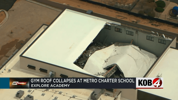
gym1_jzeshz.png


ALBUQUERQUE, N.M. — In-person classes have been canceled at a local charter school for the rest of the week after the roof of its new gym collapsed.

School officials say the new gym at the Explore Academy middle and high school campus was basically complete. They were even planning on hosting a ribbon cutting Wednesday, but that’s been canceled, as well as all in-person classes.

Parents learned about the collapse through an email from the school Sunday night.

“The students are out the whole week now,” a parent told KOB 4 anonymously. “Because they have to get inspectors to gather and, at the request of the inspectors in particular, for students to stay away until they can just look the whole thing over.”

The parent said the incident has raised many more concerns about sending her child back to school.

“Students were going to be in that building in two days, and I think one of the big questions I personally have is, did it pass the inspection already?” the parent asked.

The answer is no. KOB 4 spoke with a rep from Albuquerque’s Planning Department. They said the construction company, AIC General Contractors, failed a building frame inspection on March 6. Inspectors found the trusses bowing or bending.

The city’s Planning Department didn’t know the roof had caved in until KOB 4 called Monday afternoon.

Explore Academy leaders say, as of now, it’s just the new gym that seems to be impacted, but they aren’t taking any chances.

“They discovered the damage and evaluated the situation and decided that we would go ahead and go to asynchronous learning until we have a sign off that the entire building and structure is, in fact, safe for students to enter,” said Katia Pride, Explore Academy’s director of outreach.

Pride said there was no obvious damage to nearby classrooms. The school will also have to bring in an engineering company to create a repair plan.

The city’s Planning Department will be sending a building complaints investigator to figure out what went wrong.
 
Replies continue below

Recommended for you

Those missing diagonals probably converted the girders from structures into mechanisms. If they'd have put them in the middle where the shear is lowest, they probably would have gotten away with it.
 
Gotten away with what? Saving a few bucks? What purpose was served, other than cost saving, to not including the additional diagonal braces?

John R. Baker, P.E. (ret)
Irvine, CA
Siemens PLM:

The secret of life is not finding someone to live with
It's finding someone you can't live without
 
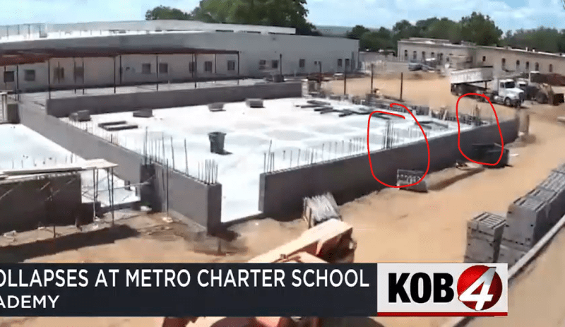
If you're interested in the full constructon time lapse see here
There looks to be quite a lot of spare room as they swing the main truss in place sitting on some rather thin looking CMU inner columns

Remember - More details = better answers
Also: If you get a response it's polite to respond to it.
 
They had to jamb the first end deep into the wall pocket to get swing clearance for the opposite end. Video doesn't show them pulling the first end back out after setting the second end. So it's possible the second end had inadequate bearing length.
 
hpaircraft said:
Those missing diagonals probably converted the girders from structures into mechanisms. If they'd have put them in the middle where the shear is lowest, they probably would have gotten away with it.
A Howe truss is made of triangles, the the members have no bending loads, and the member ends can be approximated as pins in calculations.
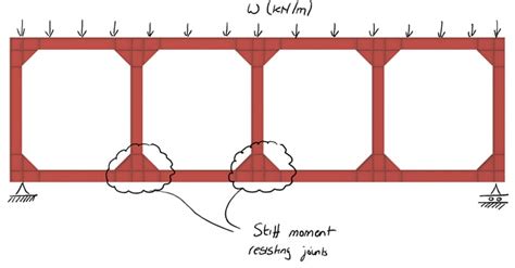
The windows put a Vierendeel truss section into a Howe truss. All of the load in the Vierendeel section creates moment loads in the connections, and bending loads in the beam which are not present in the Howe truss section.
It is possible to design this so it will work, but it is a lot more than just removing the diagonal. As all of the members appear to be rectangular structural tube it is possible these considerations were made, we will need to wait for more news.
The beam seats do look a bit sketchy. Is there a steel post hiding in the masonry? If so it must be close to Euler's slenderness limit.
 
There doesn't appear to be a steel post in the CMU.

Pilasters_m4g8hb.png
 
No need for a steel "post" in a masonry pilaster, but there is need for adequate bearing length as bones mentions.

Not an ICC tornado shelter, that's for sure. Can't even hold up sunlight.
 
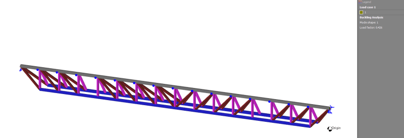
As many has observed the loss of end bearing seems the final trigger of collapse, but the question then arises what caused this and why. At first I believed the missing diagonals were a red herring and a distraction. But a brief analysis suggests otherwise

The missing diagonal could be critical but not for the obvious reasons. The obvious reason being the large loss of strength when fully restrained. (Approximately a 1/3.) The non obvious reason is that they increase the buckling likelihood of the truss by approximately 40x at ULS! (presuming the bottom chord is unrestrained)

When the bottom chord is under tension it has no obvious desire to buckle. However as soon as you remove one diagonal the chords are now subject to significant bending moments and entire truss is subject to lateral torsional buckling. Furthermore my brief analysis suggests this behaviour is quite non-linear.

temp_vmugr1.png

My analysis is superficial and brief.

However I will go out on a limb and suggest this was a case of lateral torsional buckling of the truss due to an unrestrained bottom flange. This buckling caused distortion that ultimate loss of bearing. The final trusses mostly look in good condition because the LTB stayed within the elastic zone.
 
I do love to see a spacegass model. Probably my favourite software, always so intuitive and clean looking

----------------------------------------------------------------------

Why yes, I do in fact have no idea what I'm talking about
 
JohnRBaker said:
Gotten away with what? Saving a few bucks? What purpose was served, other than cost saving, to not including the additional diagonal braces?

Yeah, good question. My suspicion is that they wanted those clear spaces for services like HVAC ducting. And again, if they'd run them through the inboard two bays of the truss where the shear is negligible, the bending stiffness of the chords alone probably would have reacted what little shear was applied by the lateral trusses across their tops. Instead, they eliminated the diagonals from bays near the support ends, so in those areas the chords alone have to react the accumulated shear loads of all the lateral trusses inboard of them.
 
I agree. The diagonal braces were cleared for HVAC ducting. And despite the poor choice of location, I'm currently giving the engineers enough credit that they did for SOME of the effects of removing those diagonals. The obvious effects are the chord and strut bending of the vierendeel truss action.

The less obvious effects is changes to the global buckling behaviour of the truss. (Which to be honest I don't fully grasp myself. Except that my brief analysis shows that the truss is quite sensitive to it. (Also there often exists the notion that a tension chord/flange doesn't need to be braced to prevent LTB. This is mostly the case, but not always.

Tension buckling exists! As does LTB with unrestrained tension members. **

**Though you could just as easily claim this is simply sway of the struts under compression with limited rotational restraint on the top chord and not lateral restrain on the bottom. In reality though buckling is often a SYSTEM phenomenon. A tendency for the system to more to a lower energy state. In this case I'd describe it a LTB of the truss.
 
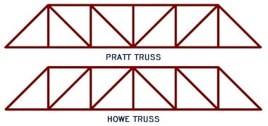
Just one correction to the terminology: these are not Howe trusses, but rather Pratt. At least for gravity loading, for net uplift they would be Howe. Pedantic, but after all, this is an engineering website.
 
Human909 your analysis appears to be a bit off. According to the photos, the omitted diagonal is in the second fully rectangular bay from each end, not in the third as your diagram shows. So you have underestimated the shear in the bay with the omitted diagonal.
 
My first thought about the missing diagonals was also that they provided space for HVAC ducts.

However, there is no duct wreckage in the post collapse images. Maybe they were going to open the guy without the ducts, and put them in later. Wouldn't be the first time that a building opened before it was finished.
 
The inspection timeline is as follows:

Screenshot_at_2024-04-22_18-39-29.timeline_assxva.jpg


March 6 - structural inspection fails citing dip in truss
- interior work allowed to proceed​

March 25 - followup inspection fails citing further dip in truss
- interior work suspended
- third party evaluation required​

April 7 - roof collapse

April 8 - news contacts city for comments only to find city unaware of the collapse

April 10 - planned ribbon cutting cancelled

[URL unfurl="true" said:
https://citydesk.org/2024/charter-school-roof-collapses/[/URL]]“Students were NOT going to be actively using the building this week regardless of the ribbon cutting,” Kolander wrote. “We needed the gas lines to be activated, the flooring to finish being installed, final inspections to be done, etc. I know it was made to seem that kids were days away from using the building, but that is not accurate on anyone’s timeline.”


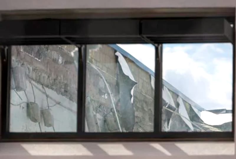
I'm not familiar with roof space details in hot climates. There appears to be a deep section of unfinished space beneath the roof surface layer and interior space beneath. There appears to be a great deal of material (see my 3d photo posted above) in the debris pile that may be insulation material. Also, in the photo below, embedded rebar at the interior finish level seems to have concrete adhering to it?

window_view.6615bd6140f4c_v7ht2k.jpg


Nonetheless, the omitted diagonals in the girder truss would create significant moments at the four corners of the bay. Where the web elements are slender HSS and the chords are broad HSS, this becomes a particularly challenging connection to detail and if not adequately fabricated provides a mechanism for the truss to sag. Additionally, it isn't beyond reason to believe that the sagging truss tore out the bearing connection at the nearest wall contact.
 
OK Prat trusses with the ends inverted,
Pratt_Howe_Trusses-347551232_cjdv0s.jpg

It seems the point I was trying to make is finding some consensus IE the Vierendeel truss stuck into a truss built with two force members is a significant design challenge, with a bunch of potential pitfalls.
th-3400078326_u2vwcv.jpg
 
Yes, of course it is difficult, if not impractical. There is always some moment transfer even when trusses are triangulated throughout, but the ductility of steel means the hinged assumption works, conservatively. No so much with concrete structures like the FIU pedestrian bridge.
 
hpaircraft said:
Human909 your analysis appears to be a bit off. According to the photos, the omitted diagonal is in the second fully rectangular bay from each end, not in the third as your diagram shows. So you have underestimated the shear in the bay with the omitted diagonal.
True. But I don't think this affect the conclusions. I don't believe this failure was caused by member failure due to the missing diagonal brace. The loads here were well below ULS loads. I think the more likely conclusion is LATERAL TORSIONAL BUCKLING resulting in the truss pulling away from its support.

hokie66 said:
Yes, of course it is difficult, if not impractical. There is always some moment transfer even when trusses are triangulated throughout, but the ductility of steel means the hinged assumption works, conservatively. No so much with concrete structures like the FIU pedestrian bridge.
Agreed. In fact when I design HSS trusses I model it with rigid connected ends and there is non negligible moment transferred. Why? Because that is the reality of most welded truss HSS construction. Those ends are moment connected not pinned.

In a normal truss with full diagonals throughout then that moment transfer plays a minor role and there is no great difference between pinned and rigid connection. But given we now have plenty of computational power at our disposal, it would seem amiss not to consider it.
 
Human909,

Unless I've misunderstood your diagram, you seem to have looked at a triangular section truss?

It's very clear this is only one plane.

The inspection report seems to indicate a gradual yielding or creep of the truss or its supports.

Remember - More details = better answers
Also: If you get a response it's polite to respond to it.
 
No. There is only one truss modelled. What you are seeing is the truss and the deflected shape of the first buckling mode. I tried to view it from an angle that made that more clear, but it wasn't perfect.
 
Status
Not open for further replies.

Part and Inventory Search

Sponsor