Continue to Site

Eng-Tips is the largest engineering community on the Internet

Intelligent Work Forums for Engineering Professionals

  • Congratulations KootK on being selected by the Eng-Tips community for having the most helpful posts in the forums last week. Way to Go!

Newly Constructed Gym Has Roof Collapse in New Mexico 12

Status
Not open for further replies.

jerseyshore

Structural
May 14, 2015
711

gym1_jzeshz.png


ALBUQUERQUE, N.M. — In-person classes have been canceled at a local charter school for the rest of the week after the roof of its new gym collapsed.

School officials say the new gym at the Explore Academy middle and high school campus was basically complete. They were even planning on hosting a ribbon cutting Wednesday, but that’s been canceled, as well as all in-person classes.

Parents learned about the collapse through an email from the school Sunday night.

“The students are out the whole week now,” a parent told KOB 4 anonymously. “Because they have to get inspectors to gather and, at the request of the inspectors in particular, for students to stay away until they can just look the whole thing over.”

The parent said the incident has raised many more concerns about sending her child back to school.

“Students were going to be in that building in two days, and I think one of the big questions I personally have is, did it pass the inspection already?” the parent asked.

The answer is no. KOB 4 spoke with a rep from Albuquerque’s Planning Department. They said the construction company, AIC General Contractors, failed a building frame inspection on March 6. Inspectors found the trusses bowing or bending.

The city’s Planning Department didn’t know the roof had caved in until KOB 4 called Monday afternoon.

Explore Academy leaders say, as of now, it’s just the new gym that seems to be impacted, but they aren’t taking any chances.

“They discovered the damage and evaluated the situation and decided that we would go ahead and go to asynchronous learning until we have a sign off that the entire building and structure is, in fact, safe for students to enter,” said Katia Pride, Explore Academy’s director of outreach.

Pride said there was no obvious damage to nearby classrooms. The school will also have to bring in an engineering company to create a repair plan.

The city’s Planning Department will be sending a building complaints investigator to figure out what went wrong.

 
Replies continue below

Recommended for you

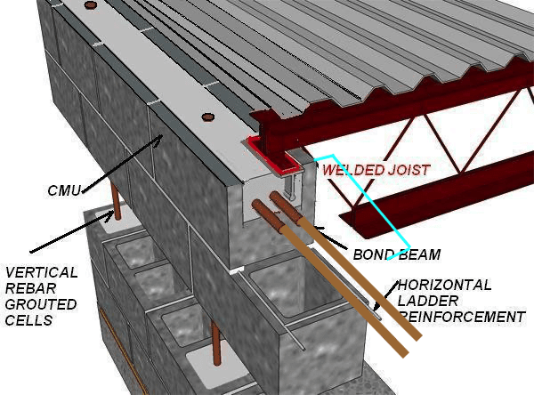
JLNJ, Steel Truss should bear on embedded steel plate that is on top of horizontally reinforced concrete/grouted bond beam, and not lintel block outer edge. Drawing above shows this clearly. Joist is resting on reinforced grouted portion of lintel.

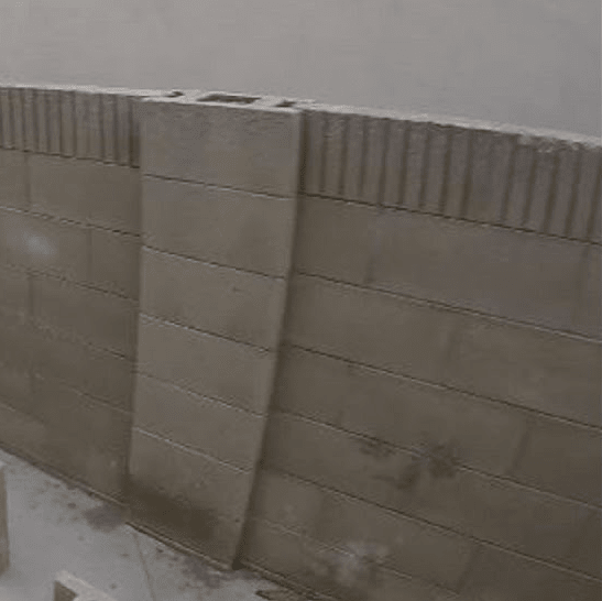
Brad, I realize you are guess at block size of wall, and from images it appears that pilaster is about 2" deeper than wall. 10" and 12" blocks would fit that scenario....

It appears Hollow Core Planks only require 3" of bearing depth, so my question is how much bearing depth does a very large steel truss point load require and well as width? Even when blocking mobile homes, aka trailers, in my teens, we never bottle jacked directly on a the concrete block..... We always spread that load with at least a 2x8/10/12 depending on block depth.


Perhaps adding a blue pilaster line and extended rebars would explain why tension horizontal rebar is not directly under extended grouted area of pilaster, whereas if full 12" deep wall, rebar locations would be in better location to assist in spreading bearing load evenly.

Untitled_obh7ov_fhml64.png
 
Just because you found a detail online that shows a truss supported a certain way doesn't mean that is the only way trusses are allowed to be supported...
 
Never said it did, but it is hard to explain the top of block pilaster been destroyed if the metal plate extended out over block edge. The whole concrete block pilaster design looks like a very poor design choice...
 
Oops said:
so my question is how much bearing depth does a very large steel truss point load require and well as width?

As you’re seeing here, it is a subject of some disagreement. The bottom line is that it needs enough effective bearing area to prevent bearing failure.

You can get wildly different answers depending on your bearing assumptions. The actual concrete bearing stresses depend heavily on eccentricity and assumed contact area.

As you note, steel bearing plates are common, to assure a certain bearing area. It’s not essential, but can be a good idea. There are many corbels and seats out there where the front edge is starting to crumble off due to concentrated bearing at the outer edge.
 
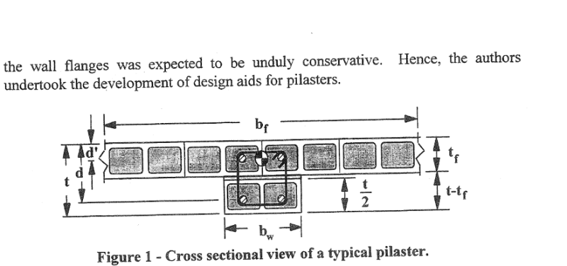
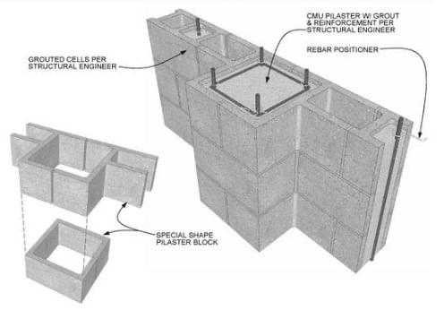
So it is clear, below is what a pilaster typically looks like. All you are showing in your wall section can be done at the head of the pilaster. Pilasters generally serve two purposes. The first is to support large point loads, and second is to allow for a thinner wall section or less solids in that wall section. I think the scale of the images makes it difficult to discern dimensions.

PILASTER_qiz9ki.png
 
Tom and Brad,

I appreciate your input, and Tom you confirm my thoughts about outer edge bearing problems.

Brad in your typically concrete block pilaster cross section, how do you put the rebar stirrup wraps in a masonry pilaster wall that just adds another equal width block adjacent to wall, where you have a point load?

I can see cutting out sides of block between wall and pilaster at stirrup locations, perhaps that is solution?

Also now way can I see more than 2-4" protrusion from wall of pilaster, from the low resolution images, rather than another 8 or 10" block pilaster. Looking at construction sequence on KOB, it appears they are stuffing more steel in block cores about every 4' of height, with more in area of point truss loads.

Can't tell what is going on with pilaster, but it appears it is being laid at same time as wall. From images it appeared to be they just laid in deep block at pilaster area, then filled cores.

 
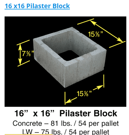
That image was from a tech journal I found. Many professors are not great at the building. Below is an example of a pilaster shape you can buy. There are other ways to make them to. The primary goal is a reinforced concrete column of known higher strength.

PILASTER-SHAPEpng_ghm4j8.png
 
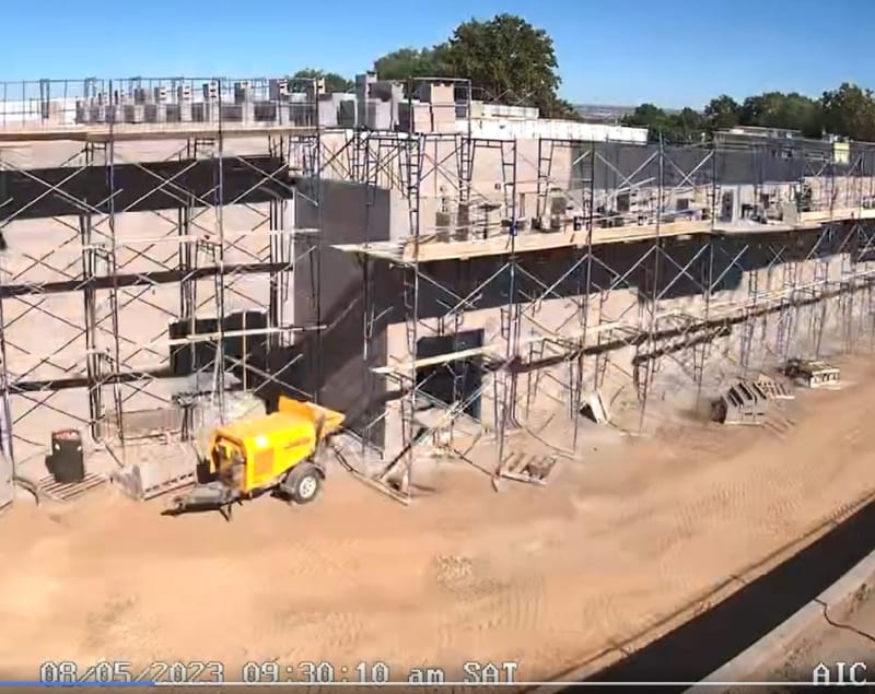
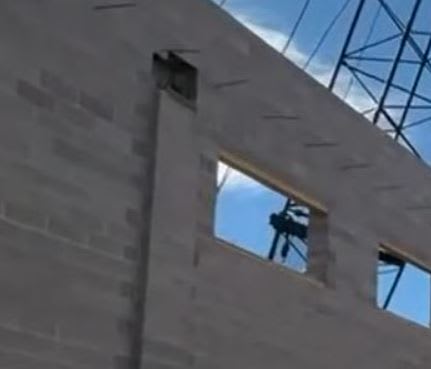
Still from one of the construction reels which appears to show U-shaped blocks.
block_pnqbxq.jpg
 
The wall appears to be constructed using 8" units...

MasonryWall_fvxaom.png


-----*****-----
So strange to see the singularity approaching while the entire planet is rapidly turning into a hellscape. -John Coates

-Dik
 
If the pilaster were masonry, most engineers would design the bearing with the support centre of the large truss falling on the centerline of the pilaster or on the centroid of the composite wall-pilaster section. They would avoid eccentricities for the large truss load. There would be a steel bearing plate of sufficient area to accommodate the bearing with headed studs or welded rebar going into the pilaster. Depending on the code, the composite section would be determined by the pilaster width + 12 x the thickness of the wall or the height of the wall / 12 + pilaster width, whichever is less. Strength would be determined on this... This composite section should easily be capable of supporting roof loads (I'm not so sure for HC slabs which weigh more than 2x a regular roof. This is based on experience with regular roof loads for a building of similar geometry. Pilasters designed properly can easily work for normal roofs.). The pilaster would be designed as a regular masonry column with windload plus a nominal eccentricity from the truss... that's the way I would have designed it (we don't have significant seismic loadings in this area). No rocket science and design level of difficulty out of 10 would be about 3.

-----*****-----
So strange to see the singularity approaching while the entire planet is rapidly turning into a hellscape. -John Coates

-Dik
 
dik said:
The wall appears to be constructed using 8" units...

That makes sense. And if so, the pilasters appears to be less than 8"?.

seat_hl3zpp.jpg


The actual load is around 600kN based on scaling off google maps, and assuming 200 planks and normal topping. (someone else also estimated 140kips above)

That's a lot of load on a small pilaster, assuming it wasn't armored with bearing plates as you discussed above.
 
I'll see if I can dig up my SMath program...

Do you have the span of the truss and spacing? Do you have the roof construction, HC slabs (55psf in these environs) cementitious topping? lightweight? insulation thickness? type? and roofing membrane. M & E loads? 3 or 4 psf?

Else I'll mod the program to put in different values.

-----*****-----
So strange to see the singularity approaching while the entire planet is rapidly turning into a hellscape. -John Coates

-Dik
 
Based off Google maps the truss span is ~25m and spacing ~10m

I don’t know the construction details. I assumed 200mm planks plus 50mm topping.
 
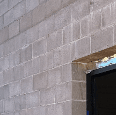
Looking at a the window jamb picture closer again, it could be 8". I sketched my guess below.

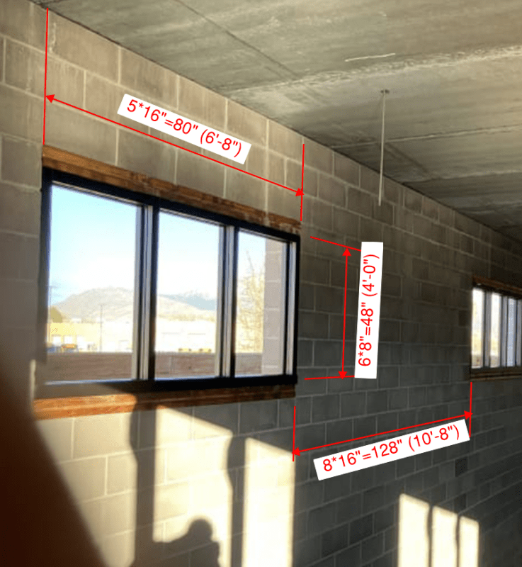
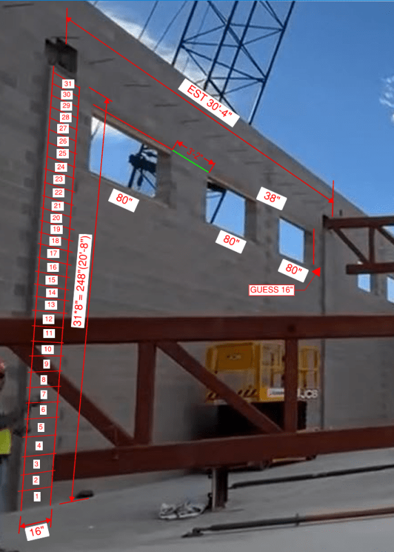
Assuming the window sizes shown in the image below is the same along the side in question, I estimated they are 80" wide. I do not see any better pictures to estimate the space between windows, so I scaled the image. Given the perspective, this could be wrong. I estimated the space between trusses is 30'-4", which is close to Tom's google earth estimate. Counting blocks, the bearing elevation of the truss seems to be approximately 20'-8".

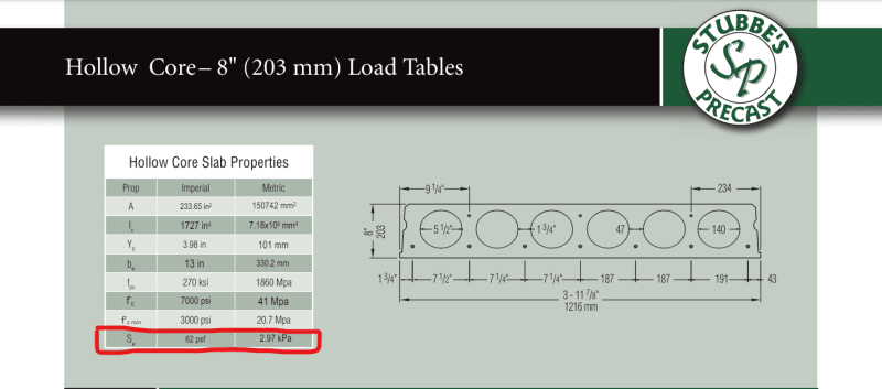
Assuming 8" Hollow Core slabs, their weight is 62psf from Stubbes. The topping thickness seems to be in question given the slopes discussed, but maybe 3" average or 37psf???

A dead load failure suggests a fundamental flaw. Here I suspect the live load is quite low, but I would hope you could load the roof to at least twice the dead loads before you had anything happen like this.

NM-WIN_w2hohm.png


NM-WIN2_dmkgmv.png


NM-HC_c2zfbq.png


NM-WIN_qgbink.png
 
Two things:

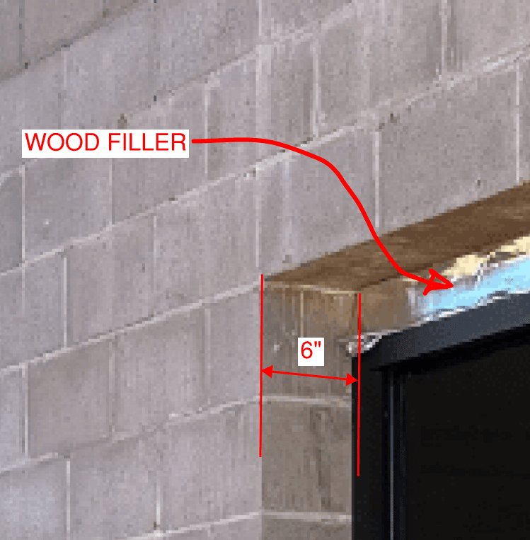
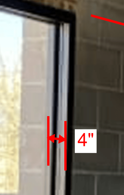
If the spposition is that the CMU's are 8" deep and your estimation is that there is a 6" reveal at the exterior of the window frame, that leaves 2" for the frame depth, which is rather shallow.

If you are using the wood window opening liner as a frame of reference and assuming double 2" standard lumber sizes, in other words a 3" liner, that is consistent with your previous estimation.

My guess is that the liner is actually augmented with a layer of 3/4" plywood (see image above, particularly along lower sill). Proportinately, the window frame depth is closer to 4" and thus, the CMU's are 10" deep.

Further, the reveal of the pilasters is quite shallow so it would be reasonable to believe them to be 12" deep and provide a 5 or 5 1/2" seat on either end for the girder.

Even further, it appears that the seat plate protrudes from the pilaster maybe 1/2" providing ample protection for the CMU lip.
 
The window frames look like 4" aluminum frames I see all the time. I suspect the wood fill is 2"x4" material. The main reason I posted the info was to entice Dik to run thru an analysis to show that the pilaster is feasible as many of us think.

NM-WIN3_iclzk7.png
 
Do you agree that the likely block depth is 10" with a pilaster depth of 12"?
 
Untitled_k7ngc4.png


A masonry reinforced concrete pilaster similar to below above, at correct size for 30' tall column, with bearing capacity to support very large point load, should work fine....Lost my bearings again!

BUT, that does not 'appear' to be the design we are seeing in the limited images and videos we have available to evaluate....

I wish I could find an image of what it appears to be in my head......


OK, image below is NOT totally accurate, but it conveys concept of just inserting 12" block in 10" block wall to add bearing area for point load. Then capping it all with U-Block Bond Beam. Trouble is you end up with eccentric load at 'Bumped Out' pilaster appearance area...... and continuous wall bond beam reinforcing is not concentric with point load bearing area.

Untitled_cxorcl.png
 
I tend to think it could be 10", but I am not sure there is much reason to delve too much into that detail. Dik mentioned a SMath sheet he has. Once he enters a few values he can change variables and determine what might have worked based on our estimates. I don't think the pilaster was the problem. I have not worked with masonry in a long time since we do not have many trades doing the work. Plus, it has lost popularity due to the energy code in Canada in my area.
 
Thanks for the dimension information...

-----*****-----
So strange to see the singularity approaching while the entire planet is rapidly turning into a hellscape. -John Coates

-Dik
 
Status
Not open for further replies.

Part and Inventory Search

Sponsor