Continue to Site

Eng-Tips is the largest engineering community on the Internet

Intelligent Work Forums for Engineering Professionals

  • Congratulations KootK on being selected by the Eng-Tips community for having the most helpful posts in the forums last week. Way to Go!

Newly Constructed Gym Has Roof Collapse in New Mexico 12

Status
Not open for further replies.

jerseyshore

Structural
May 14, 2015
713

gym1_jzeshz.png


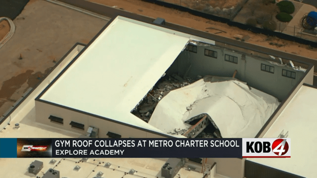
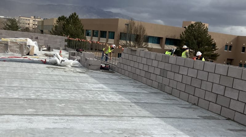
ALBUQUERQUE, N.M. — In-person classes have been canceled at a local charter school for the rest of the week after the roof of its new gym collapsed.

School officials say the new gym at the Explore Academy middle and high school campus was basically complete. They were even planning on hosting a ribbon cutting Wednesday, but that’s been canceled, as well as all in-person classes.

Parents learned about the collapse through an email from the school Sunday night.

“The students are out the whole week now,” a parent told KOB 4 anonymously. “Because they have to get inspectors to gather and, at the request of the inspectors in particular, for students to stay away until they can just look the whole thing over.”

The parent said the incident has raised many more concerns about sending her child back to school.

“Students were going to be in that building in two days, and I think one of the big questions I personally have is, did it pass the inspection already?” the parent asked.

The answer is no. KOB 4 spoke with a rep from Albuquerque’s Planning Department. They said the construction company, AIC General Contractors, failed a building frame inspection on March 6. Inspectors found the trusses bowing or bending.

The city’s Planning Department didn’t know the roof had caved in until KOB 4 called Monday afternoon.

Explore Academy leaders say, as of now, it’s just the new gym that seems to be impacted, but they aren’t taking any chances.

“They discovered the damage and evaluated the situation and decided that we would go ahead and go to asynchronous learning until we have a sign off that the entire building and structure is, in fact, safe for students to enter,” said Katia Pride, Explore Academy’s director of outreach.

Pride said there was no obvious damage to nearby classrooms. The school will also have to bring in an engineering company to create a repair plan.

The city’s Planning Department will be sending a building complaints investigator to figure out what went wrong.
 
Replies continue below

Recommended for you

I should have noticed it had a topping slab earlier, my bad.

Dik, every steel bridge with precast slabs I have seen uses studs. I would use them in a heartbeat. With todays modern technology it is not difficult to accommodate them in the design. This connection is super critical to the truss performance as you know.
 
I would guess that in all common sense they didn't pour the topping knowing there was a dip in the girder. There is evidence of the topping layer and some cables in the imagery. In any event, the insulation and membrane have to be held down either mechanically, glue or ballast. Does anyone know how this membrane is secured? Also, what is a spring tension system for the topping? Is that just supposed to relieve the weight of the topping? How much tension can be loaded into the parapet? Many questions from the uninitiated. I didn't see anything on Google.

To be clear, we are talking about a topping layer above the insulation not as part of the hollow core base?
 

Different details of construction; when was the last time you saw HC slabs used for a bridge?

-----*****-----
So strange to see the singularity approaching while the entire planet is rapidly turning into a hellscape. -John Coates

-Dik
 
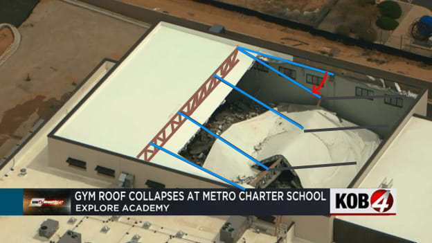
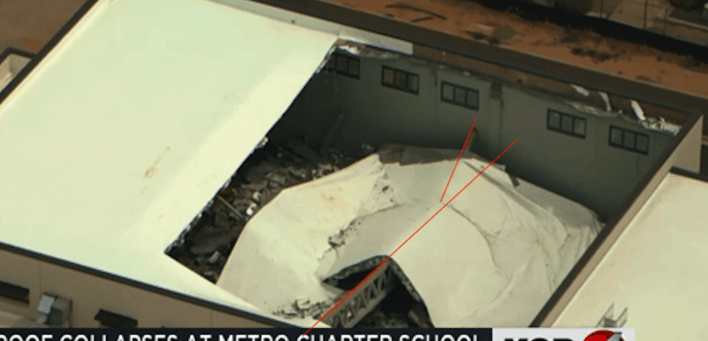
Regarding the truss ending up North of the support column. I suspect when the truss lost its bearing, the roof and truss assembly likely pivoted northward around the intact truss, due to the northern end of the failed roof still being connected there.

gym_fdw5mq.jpg
 
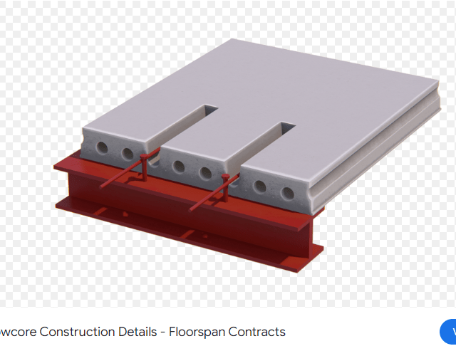
Yes, Dik, bridges do not use hollow cores, but we can use the same concept with this. Regardless, we are going off topic.

hollow_core_c5nppj.png
 
As previously posted, torsional buckling of top chord makes a lot of sense to move top chord laterally off floating bearing surface, and perhaps the asymmetrically draping and break up of the roof deck provide some more clues?

As far as duct layout, I have not seen any evidence to support how the duct was actually routed inside the gym, once it entered WEST outside wall.

Perhaps an L-shaped supply trunk ducts were used on supply to condition east wall between two roof trusses?

Perhaps return duct used the other Vierendeel truss openings to route return duct at end wall or perhaps only openings at one end of truss were to be used for duct?

Was duct hung off threaded rod, drilled into cores of hollow core deck? Better yet, since we know building was not finished, was interior duct even installed at this point?

 
Except it may be the bottom chord. The top chord is more likely to be laterally supported by the roof deck, while I have not seen any evidence of lateral support of the bottom chord.

--Einstein gave the same test to students every year. When asked why he would do something like that, "Because the answers had changed."
 
Yes. My bet is still on the movement of the bottom chord as the primary trigger to the column being pulled off its support. AKA LTB of the member The reports of inspectors seeing the truss "dipping" is on piece of early evidence. The fact it occurred at such a low load is another along with the truss seemingly mostly intact.
 
I suspect it simply fell off or slipped off the seat, perhaps due to a bearing failure or similar, as opposed to it buckling off the seat. We’ll find out soon enough once we get more pictures and details.
 
We still don't know how, or even if, the truss was secured at it's bearing.
 
There was a problem, before:

"For this gymnasium roof project, they failed a building frame inspection on March 6, and the Building Inspector required corrections related to the building’s safety. Our Building Inspectors revisited the site on the 15th to inspect progress on the corrections. While some of the construction was sufficient, our Building Inspector once again flagged a deficiency in the construction. The Building Inspector then required a secondary engineering firm to submit calculations, called a peer review, to support the building construction plans. The Building Safety Division never received such secondary engineering calculations."


-----*****-----
So strange to see the singularity approaching while the entire planet is rapidly turning into a hellscape. -John Coates

-Dik
 
from jerseyshore's comment said:
Joe Graziano commented that “the roof is a spring cable suspension system with concrete beams and poured concrete as the material over styrofoam. There is no way the cable system failed. Those walls are under tension right now and are dangerous to be near.

I have no idea what a "spring cable suspension system" is, or why any of the walls would be "under tension"...? Maybe he's referring to the remaining portion of the roof/diaphragm being under tension since there's tons of concrete just hanging out in the air?

Either way, it sounds like (based on this rather confused sounding description) it was perhaps an untopped hollowcore roof with polyiso foam insulation which was then topped with lightweight concrete. That is usually done for acoustic reasons. More so to keep sound in the building.
 
gym1_jzeshz_vbmf6a.png


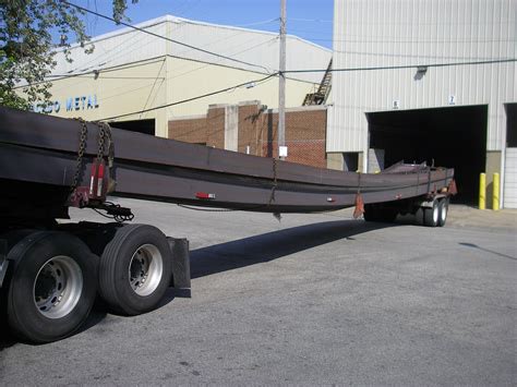
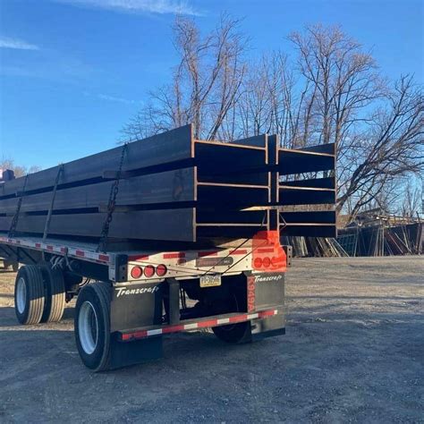
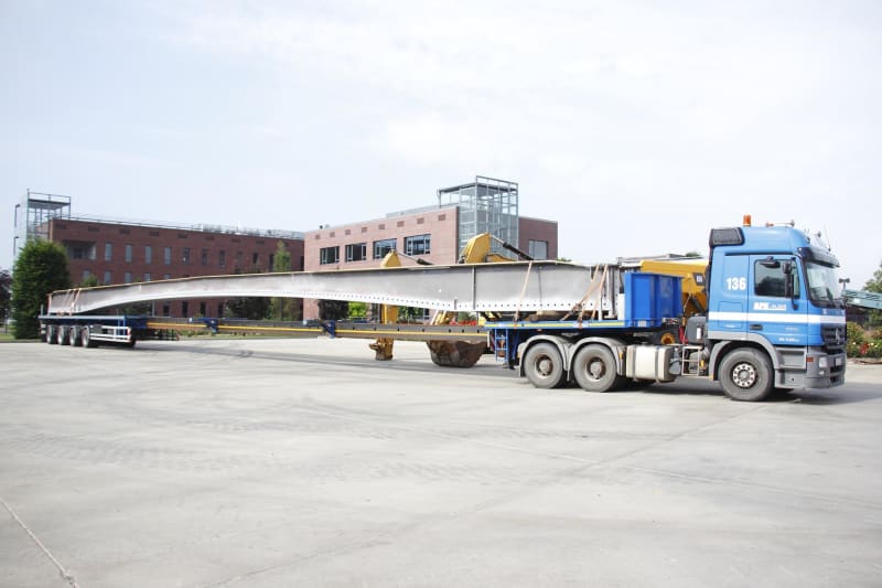
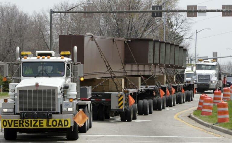
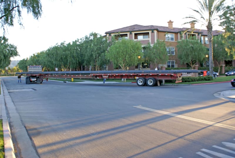
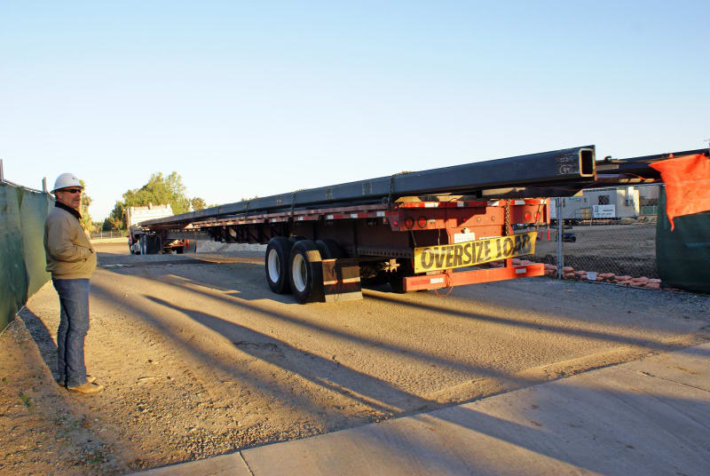
How 'did' they transport the large metal truss from fabrication to job site?

I have seen how they transport wood trusses to job sites, and they are laterally bent in all directions during transportation to job site.

How was truss stored at job site?

So could you bore-sight align truss before and after erection?

Some random options from Google images:

th-26287206_xzixtz.jpg
th-1585868033_bc5c3t.jpg
j-04-18-0853_084-306030915_girpln.jpg


536aaeb26a6ee.preview-1024-768x473_upybdb.jpg
 
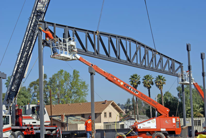
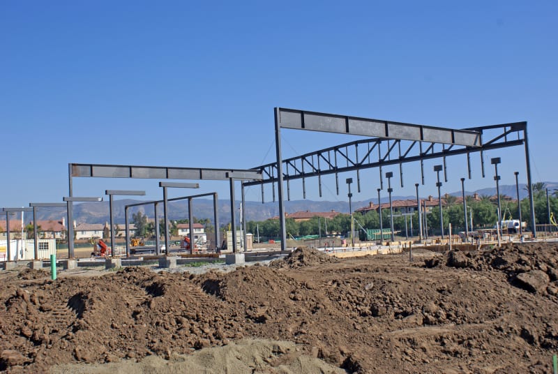
When they built our church 15 years ago, in addition to being on the building committee, I documented the construction for our parish records, going over to the job site every couple of days or when anything significant was taking place, such as the day they delivered the 80-foot long main truss for the building, as seen below:

GJ-081_y0c7na.jpg

January 2009 (Sony A100, 18-70mm)

GJ-088_v5ot3g.jpg

January 2009 (Sony A100, 18-70mm)

And I was back the day they placed it in the superstructure of the building:

GK-038_kple78.jpg

January 2009 (Sony A100, 18-70mm)

And when the basic steel superstructure was completed:

GK-067_ywcnek.jpg

January 2009 (Sony A100, 18-70mm)

And when they had installed the wooden cross trusses, which was the main support for the roof:

GN-061_kyb3l1.jpg

May 2009 (Sony A100, 18-70mm)

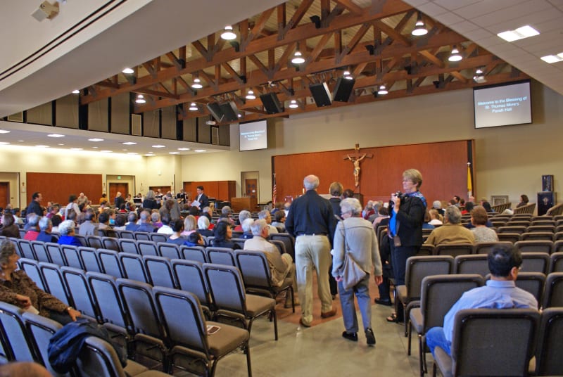
And as you can see were exposed to the congregation (this picture was taken the day the building was dedicated):

HD-008_s3g3pa.jpg

January 2010 (Sony A100, 18-70mm)

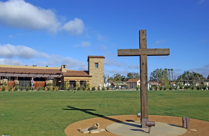
And here is what the building looks like on the outside:

HF-001_re2dcu.jpg

March 2010 (Sony A100, 10-24mm)

Note that this building is located in Southern California and therefore had to be built to strict earthquake codes.

John R. Baker, P.E. (ret)
Irvine, CA
Siemens PLM:

The secret of life is not finding someone to live with
It's finding someone you can't live without
 
Actually, are we missing something here concentrating on the truss.

What actually connects the concrete slabs to the wall and what connects them to each other resting on not a large bearing surface on the trusses.

There are some photos on this, but I can't see how the concrete panels are supported onto the CMU wall.

Did the blocks fall / fail first and then dragged the truss off its support or vice versa?

Maybe we'll never know as there isn't any public ally available CCTV footage.

Could wind load have lifted the roof through the open windows and displaced it?

Remember - More details = better answers
Also: If you get a response it's polite to respond to it.
 
The panels sit on the block wall and the parapet is built up on top, at least on the ends. Rebar and concrete plugs are used to secure them, visible in the damaged remains.

roof_panel_connection_mtih9q.jpg

Facebook

window_view.6615bd6140f4c_v7ht2k_cbi9nf.jpg
 
Hmmmm,

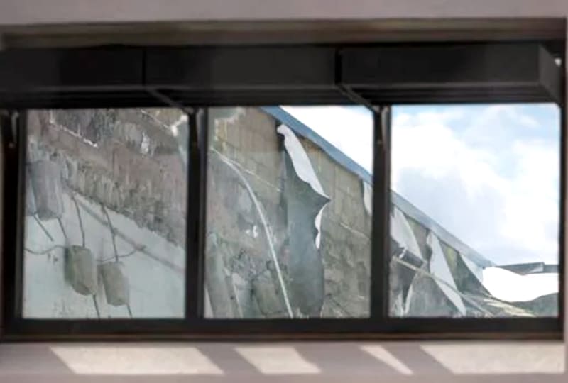
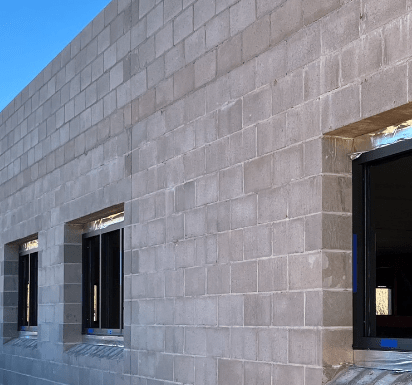
In the faceboook photos, the roof panels look about three blocks wide. Yet on the external shot of the same location all you see three block up from the top of the window frame is blocks.

So what are they actually sitting on? Half a block?

Screenshot_2024-04-30_152523_otsohp.png


Remember - More details = better answers
Also: If you get a response it's polite to respond to it.
 
Yes, they generally hold them back a few inches. That lets them a) hide it in the block coursing on the exterior by placing just a face shell along the edge and b) allows them to grout the wall and the ends of the hollow core together. There will typically be a bond beam for them to rest on with bars coming up, and hooks going into the hollow core and turned into the plane of the wall. So when the grout it, the grout flows into the hollow core (the "concrete plugs" mentioned above) and engages the bars coming out of the wall, too. It works well under design loading, but it isn't designed to hang the planks from the wall so the plugs pulled out when they dropped.
 
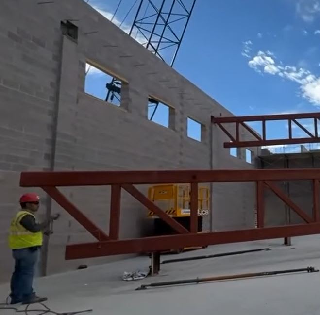
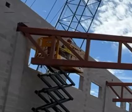
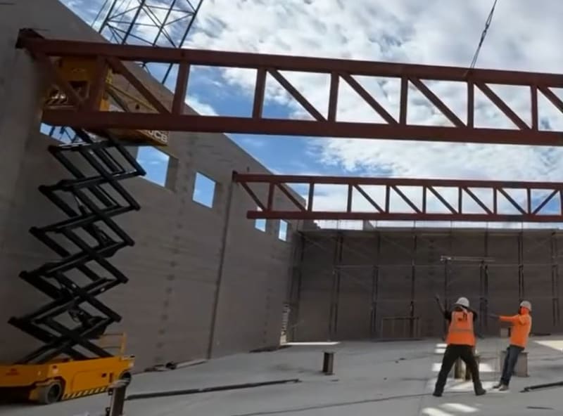
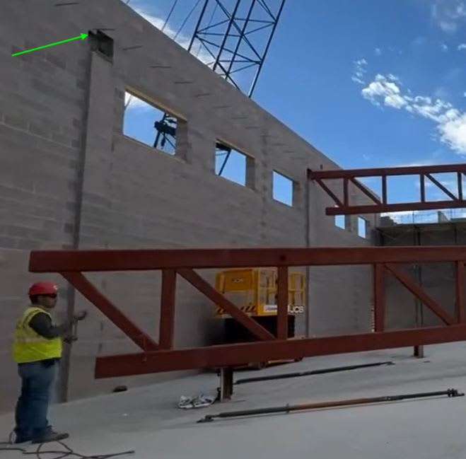
You can see in GreenLama's post above, that the bearing pocket appears to be enlarged to the left during erection, to swing truss into pocket. Looking close at the later image shows the pocket was enlarged more. Pay attention to above rebar relationship to the extended pocket area.

b1_cypnhm_burtlp.jpg
 
Status
Not open for further replies.

Part and Inventory Search

Sponsor