Continue to Site

Eng-Tips is the largest engineering community on the Internet

Intelligent Work Forums for Engineering Professionals

  • Congratulations KootK on being selected by the Eng-Tips community for having the most helpful posts in the forums last week. Way to Go!

No lateral support at the supports of a beam 5

Status
Not open for further replies.

Logan82

Structural
May 5, 2021
212
Hi,

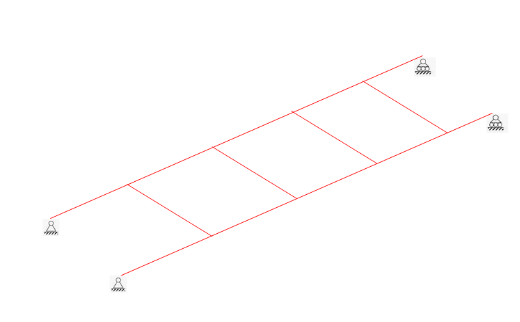
I have a situation where it is not possible to have lateral supports at one beam support of a platform. Normally it is standard practice to have lateral supports. Are there some reduction factors to apply to the resistance of this beam due to the non laterally supported beam support? There should be no torsion applied on the beam.
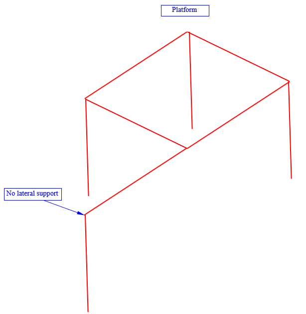
4_urx7gq.png
 
Replies continue below

Recommended for you

Provide torsional restraint at each end and midspan. Then design the beam for an unsupported length of L/2 where L is the span.

BA
 
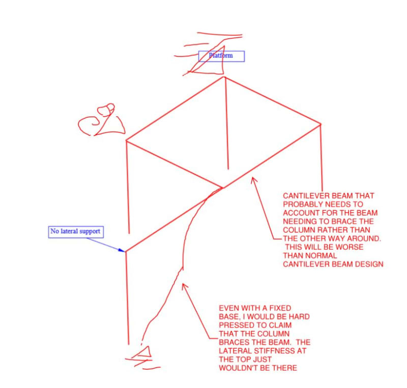
There has to be a load path. Either the column is a flagpole (cantilevered at base) and provides restraint to the beam or the beam has to provide restraint via torsion and weak axis buckling to the column.
 
Forget the beam for a minute - what is the effective length of that column?
 
The column must be capable of standing on its own, which means that it is fixed at the base. Otherwise, the design of the beam is not possible with the information given.

BA
 
What does that beam to column connection look like where the column wouldn't laterally restrain the beam?
 
Thank you all for your answers!

MIStructE_IRE, the length of the column is 2 m. It's a small platform.

The column base is fixed, and the beam to beam connection is moment stiff.

I posted this case to answer a more general question that I had in case of the absence of lateral support at a beam support. My question was brought by the fact that I don't remember seeing a case where there is no lateral support at a beam support for bridges / footbridges.

I was wondering if this configuration without lateral support at the support could be calculated with some reduction, and why it's never used.
2021-07-09_12_32_58-Document1_-_Microsoft_Word_Product_Activation_Failed_qtguqa.png


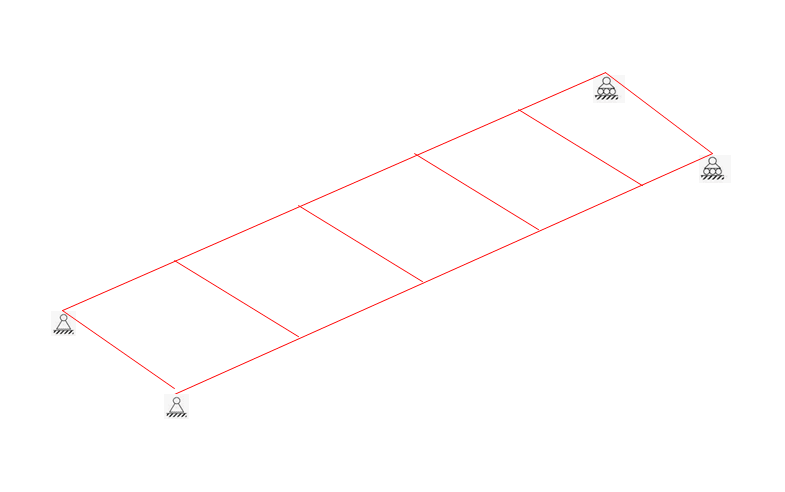
With lateral supports:
2021-07-09_12_31_37-Document1_-_Microsoft_Word_Product_Activation_Failed_z8aizg.png
 
Generally the support itself (bolt, weld, etc.) should provide the lateral support. There should be no need for an extra member between the end supports. The intermediate beams along the span are what is referred to as the bracing against lateral torsional buckling. So there is really no difference between your two cases, the second one just has two unused members (the beams between the supports).
 
I think the lateral support at the support is required according to CSA S6 2014 Canadian Highway Bridge Design Code.

2_emfcqq.png


But still I would be interested to know more about why the configuration without lateral support at the support is not allowed for bridges, while it appears to be possible for other structures.
 
vmjr24, it's good practice to frame beams into columns from two orthogonal directions. That is what Logan is referring to.

If the proper precautions are taken it's not required, but if possible I always frame into two sides. I've even added small in-fill beams in some cases to give me that second direction of framing.
 
Torsional support is required for any structure. If the pin or roller supports are at the bottom of the beam, then a transverse beam is needed to prevent rotation of the two beams framing into the end supports.

BA
 
Logan82 said:
I think the lateral support at the support is required according to CSA S6 2014 Canadian Highway Bridge Design Code.

I don't feel that provision is speaking to the same thing. I believe that provision to be speaking to how discrete lateral loads are moved downwards from the bridge deck diaphragms to the piers / abutments below. And, where that is the situation for building diaphragms, the same would apply as a matter of common sense if not prescriptive requirement. The cases that you've presented for buildings seem to speak to questions of buckling prevention restraint which is a different matter in some important ways.
 
Referring to the first post, you design it as unbraced at one end. This is sometimes called a cantilever case, but that's poor shorthand because cantilevers are often braced at the tip, and your case isn't a cantilever in the sense of vertical load.

Screenshot_20210710-084125_Box_csnjwn.jpg


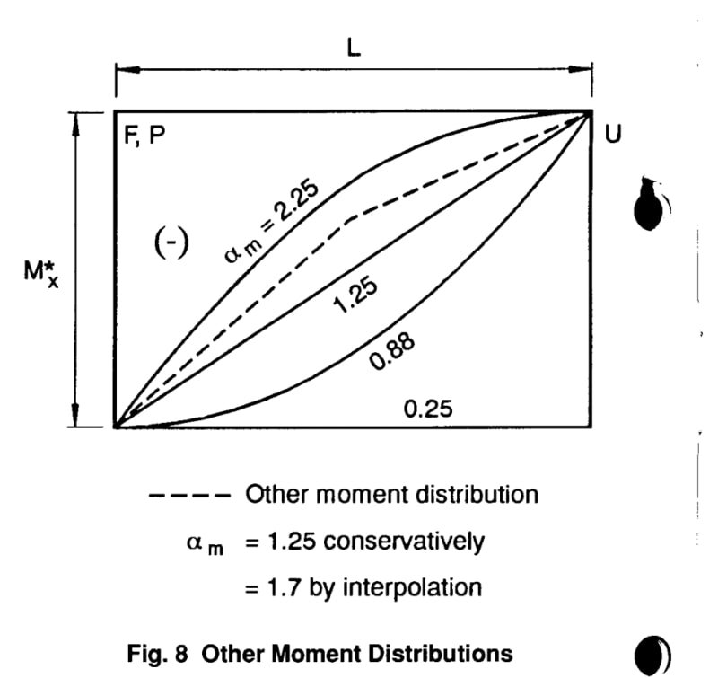
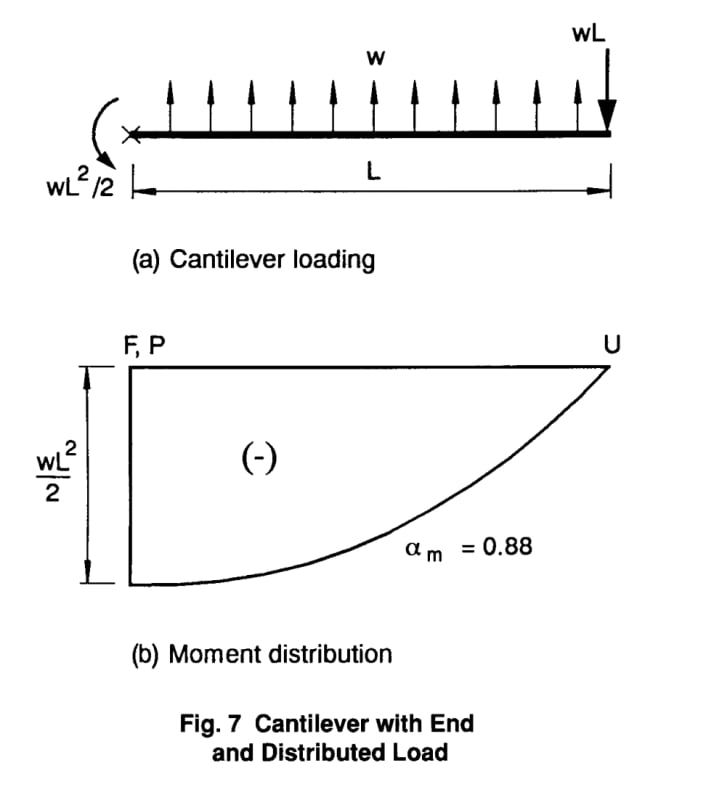
This is a diagram of the moment modification factors for one end unbraced (to Australian code but I think US/CA would be similar). The 2.25 is for UDL on a cantilever, 1.25 for tip load on cantilever, 0.25 for uniform moment, 0.88 is for UDL on 'propped cantilever' see following post. The dashed line noted as 1.7 is an arbitrary case to demonstrate interpolation between the four cases given.

This method uses the elastical critical moment for a beam laterally restrained at each end (ie it uses the same equation given in the code for 'typical' beams), not the critical moment for unrestrained at one end.
 
Also with reference to the initial sketch:

1) If this platform is laterally stabilized by moment frames, I don't feel that any form of conventional hand calculation can be used to adequately check the stability of the beam unless those moment frames are stiff enough to satisfy the requirements of something like AISC appendix 6. If those moment frames would be flexibile:

a) One might be able to apply the alignment chart method somehow but man would they need to be a skilled practitioner at that.

b) Nowadays, I would definitely favor and FEM buckling analysis.

2) If the rigid, lateral restraints that I've penciled in below are reasonable assumptions, then I see things as I've shown them in the sketch below.

C01_bne7aa.jpg
 
I overlooked that there's no column at the middle of the long beam span until KootK started talking about overall stability. Bear this in mind when reading my earlier posts.
 
A path that I feel a lot of engineers might take were it not feasible for the beam to brace the post as a pin ended column:

1) Design the post as a flagpole column with no consideration to the post needing to brace the beam.

2) Design the beam as a cantilever with no consideration to the beam needing to brace the post.

This certainly moves the needle in the right direction but, frankly, I struggle to prove to myself that it would be universally conservative. At the end of the day, the beam and column are truly a coupled system from a stability perspective.

Another treatment might be to design the post as flagpole and bracing the beam as follows:

1) Reduced base fixity to account for reasonable flexibility there:

2) 2% of beam reaction applied laterally to the top of the post.

3) AISC app 6 check on lateral stiffness of top of post.

4) AISC app 6 check on rotational stiffness of top of post.

 
Is 2% a rule of thumb for situations like this? AISC says to use 0.2% for the notional load (1/500 out-of-plumbness), so I was going to suggest that they should do a second order analysis with that load applied at the top of the post. Since the platform is small, though, it may just be an end reaction of around 10 kip, so the 0.2% lateral load is just 20 lbs, which would be pretty insignificant.

Structural Central
 
With the information given in the opening post, we cannot tell whether or not the beam is adequately braced by the column. If the column is stiff and is fixed at its base or otherwise braced, and if there are stiffeners within the beam, there is no issue.

KootK states he would be hard pressed to say the column braces the beam. Why is that? It may be okay, if only we knew a few more details about the structure including loads, geometry and member sizes.

BA
 
2% is a rule of thumb. The notional load business is different in that it's really an instability instigator, rather than an estimate of the bracing demand. Also keep in mind that the critical thing here is not the strength of the column for the 2% but, rather, the stiffness of the column top for the 2%.

I like the look of your software by the way. It's quite similar to a project that I've been longing to undertake.
 
Status
Not open for further replies.

Part and Inventory Search

Sponsor