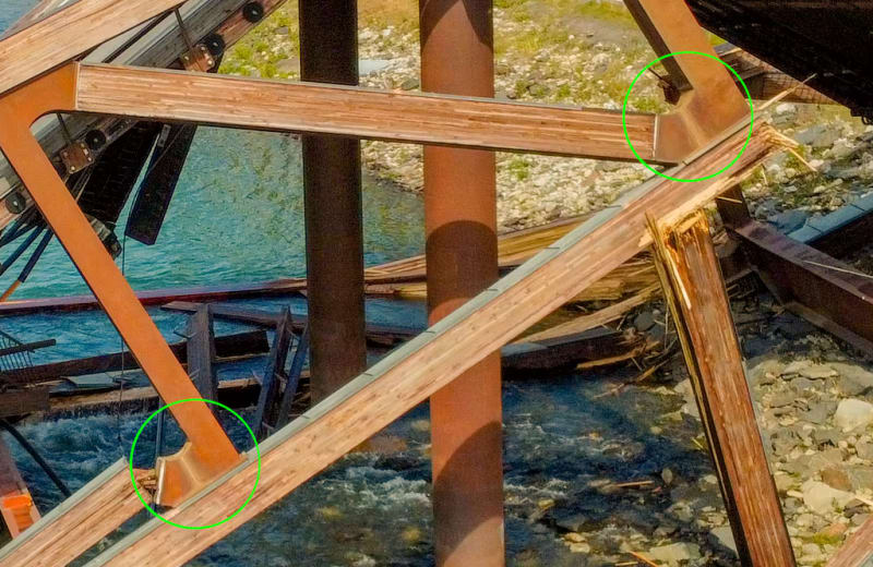
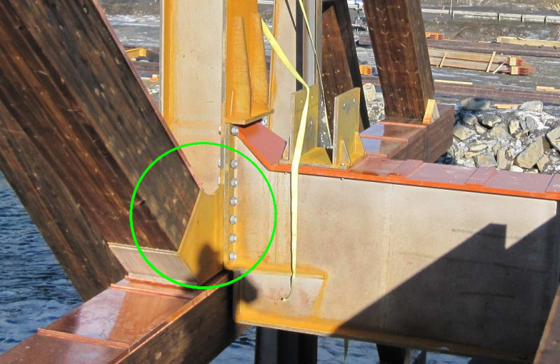
I have not seen this posted.
Navigation
Install the app
How to install the app on iOS
Follow along with the video below to see how to install our site as a web app on your home screen.
Note: This feature may not be available in some browsers.
More options
Style variation
-
Congratulations MintJulep on being selected by the Eng-Tips community for having the most helpful posts in the forums last week. Way to Go!
You are using an out of date browser. It may not display this or other websites correctly.
You should upgrade or use an alternative browser.
You should upgrade or use an alternative browser.
Norway bridge collapse 17
- Thread starter dylansdad
- Start date
- Status
- Not open for further replies.
I'm not that sure, I think with the Florida bridge, the design was improper, and it wasn't a matter of misinterpreting the computer model, or constructing it a proper fashion. When signs of distress occurred, they did nothing.
So strange to see the singularity approaching while the entire planet is rapidly turning into a hellscape. -John Coates
-Dik
I believe, if a computer model was misinterpreted for the Tretten bridge, that WOULD mean the design was improper.
And if the bridge was constructed improperly, the designer (and likely others) should have caught it and corrected the construction. They DID visit the site to supervise the assembly of their creation, didn't they?
I WILL let the designer off the hook if there was skulduggery afoot. Things like intentionally using inferior material that is impossible to detect.
I'm gonna go with improper design.
spsalso
...not the construction, the design. It didn't matter how well it was constructed. I generally don't expect the contractor to be an expert at design, only construction.
So strange to see the singularity approaching while the entire planet is rapidly turning into a hellscape. -John Coates
-Dik
So strange to see the singularity approaching while the entire planet is rapidly turning into a hellscape. -John Coates
-Dik
-
1
- #184
I think failure of "...constructing it [in] a proper fashion.", if referring to the approach of the designer, would still mean a failure of design.
Anyway.
I found it sort of amusing when the architects said:
“We have designed most of the larger wooden bridges in Norway as well as many smaller wooden bridges,” said Plan Arkitekter partner Oddmund Engh. “Our contribution to the bridge design is only concept and aesthetics, not calculations or construction drawings. This was a bridge that we were proud of.”
So. You're saying you did concept: Should cross river with a roadway and walking path. Check!
And aesthetics: Let's draw something that's pretty and way cool. Check!!
And then hand the pictures to some non-aesthete to do the grubby work of turning our pictures into a monument to, uh, us.
I have some colored pencils and some paper. I could be a bridge designer too.
Later: Got my crankypants cinched up pretty tight, there!
But it does bother me that they were quite willing to take credit for DESIGNING the bridge before it fell down. But now they're trying to put some real distance between it and them. Mighta been better to say: "We're really sad that a bridge we were involved with building failed. We are devastated, and we apologize. We don't yet know what happened to cause the failure. As troubling as this event was, we hope to learn from it. We are glad no one got seriously injured--a bright spot in a pretty grey event."
Just a thought.
spsalso
I've been calling these Vanity Bridges. And since they are, pretty much by definition, unusual, there's a lot of "it hasn't been done yet, but don't worry, everything will be fine."
Of the ones that I've "collected" (that have failed), there's this one, the Florida one, the Genoa one and the Hickory NC one.
(funny thing about the Hickory is that the real bridge is in fine shape; it's the decoration (which I did think was pretty neat) which failed)
Going the other direction, there's the railroad bridges of North America: wood trestles, steel trestles, girder spans, and truss spans. That describes probably 99% of the pre-concrete railroad bridges. Oh, yeah: and some masonry arches.
Not many architects had a hand in those. And when they did, I think they were more "advisors" to the design engineers. What's the cheapest way you can reliably cross that space?
There's nothing wrong with making gee-whiz bang special bridges. But don't screw up! That Genoa bridge--concrete in tension (yeah, I know there was steel inside, just rusting from the first day). And that moronic Florida bridge because college students don't know how to cross the street?
It all seems about ego. We gotta have a Special Bridge.
ah, well. Dinner calls, so I say adios.
spsalso
Time to get back to fundamentals.
Sullivan was an architect.Whether it be the sweeping eagle in his flight, or the open apple-blossom, the toiling work-horse, the blithe swan, the branching oak, the winding stream at its base, the drifting clouds, over all the coursing sun, form ever follows function, and this is the law. Where function does not change, form does not change. The granite rocks, the ever-brooding hills, remain for ages; the lightning lives, comes into shape, and dies, in a twinkling.
It is the pervading law of all things organic and inorganic, of all things physical and metaphysical, of all things human and all things superhuman, of all true manifestations of the head, of the heart, of the soul, that the life is recognizable in its expression, that form ever follows function. This is the law.
Further to my previous animation, which would require the lower chord of the center span to stretch, is there anything preventing the following motion from happening, given sliding bearing pads? The 5x2 pin pattern at the node on the stone support wouldn't offer much resistance.
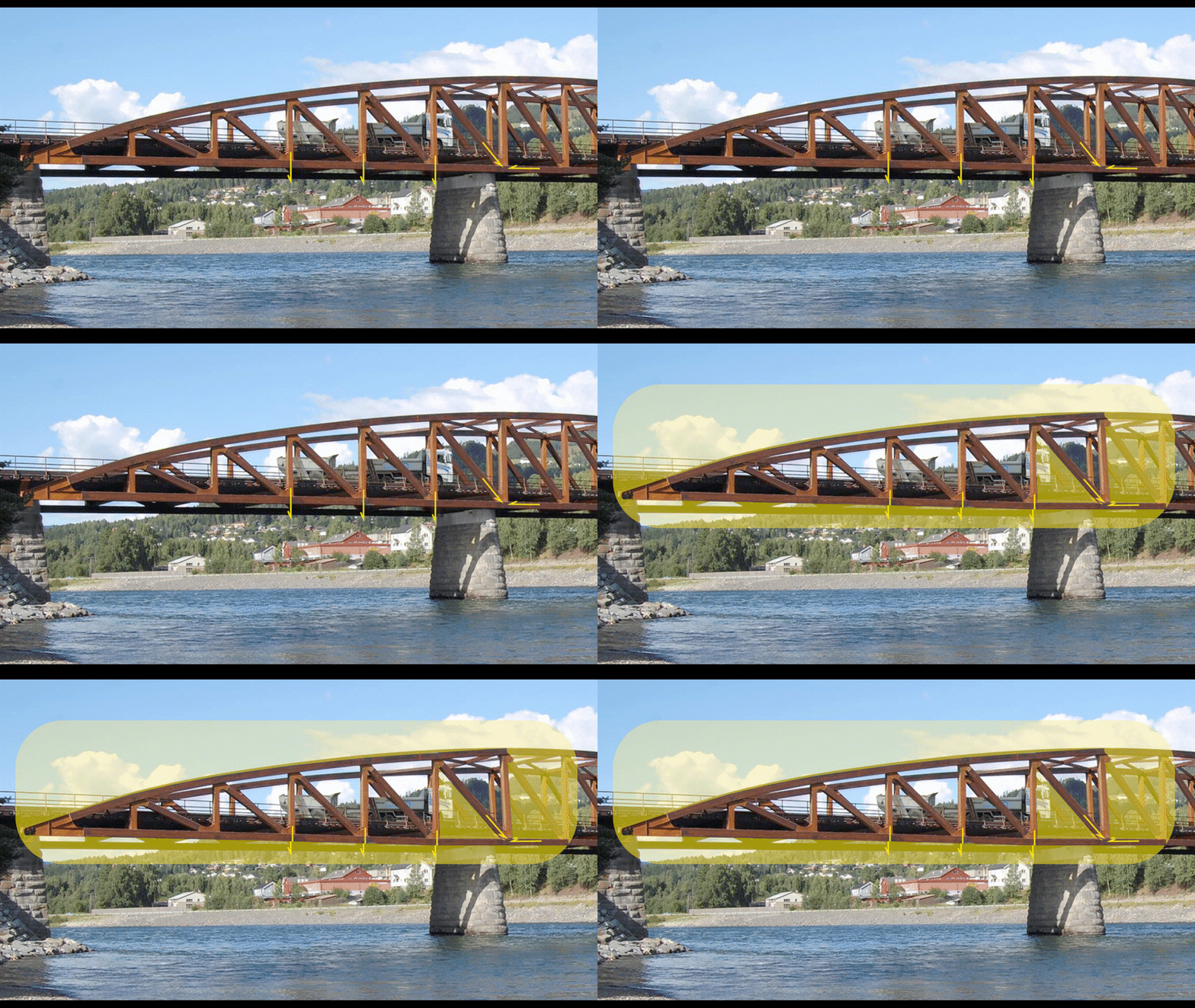


spsalso (Electrical) 21 Sep 22 03:54 said:... what I'm missing
My previous effort imagining the center span to initiate the collapse doesn't work because it required the lower chord to stretch. This progression doesn't require any elements to stretch or compress, at least not to any significant degree. The westernmost truss node is free to move east and nodes 11, 12, 14, and 15 can all flex enough to accommodate the western span downward deflection. That leaves node 13, which is not clearly indicated in the animation.
My theory is that the steel support frame (the cross beam and two vertical elements) at the stone support pushes east (at node 13) across the support causing the slotted-in steel plate and pin connection to tear the lower truss chord effectively eliminating that connection point. The chord doesn't have to drop away from the node, it just has to be ineffective or "shredded". The chord will still exist momentarily until it succumbs to the compression between nodes 11 and 15 (and the pin arrangement at the node likely served to split the chord).
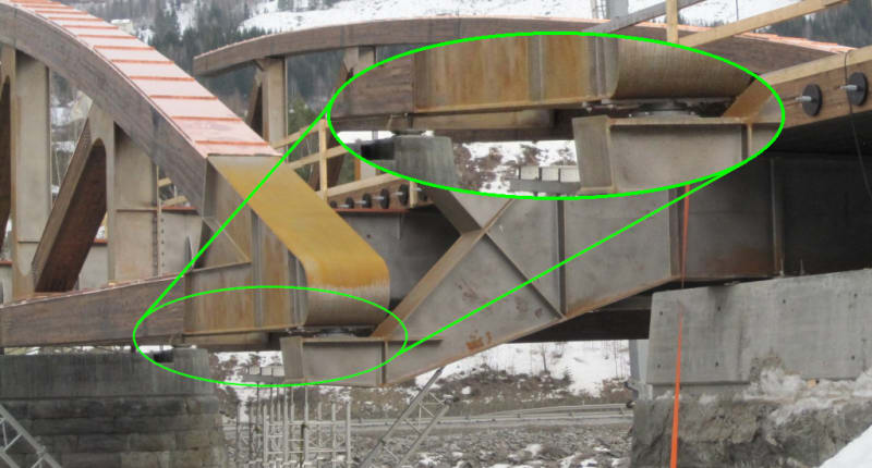
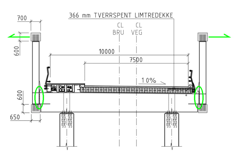
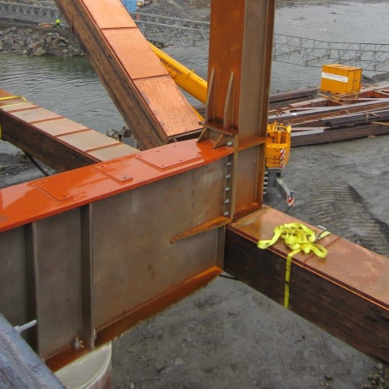
Once the structure is diminished to this extent, the self weight of the west span will continue to push the supported frame off the support as the lorry moves to the center span. From there the center span will sag and snap off at node 14. As I was proposing earlier, as the center span sags and starts to drop, it pivots about the steel column support at its east end. This will cause the two trusses to splay out (above the steel column support) and detach the bolted connections between the cross beam and vertical elements.
Edit: I had east and west mixed up. It's fixed now. (The image is of the western span of the bridge)
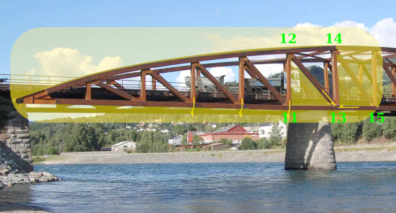
To summarize, my theory is that the collapse initiated with damage to node 13. Though the lorry was the final straw, the damage was likely accumulated during the short life of the structure, and likely punctuated by a few exceptional loads as have been documented. This incident, resulting in the collapse, likely started as the lorry proceeded across the western span.
Thanks to Lars Skaug for uploading his images to Facebook.
The Accident Investigation Board is investigating bolts on Tretten bridge that broke at 90 degrees after overloading
Paywall article
havarikommisjonen undersoker bolter pa tretten bru gikk i 90 graders skjaerbrudd etter overbelastning
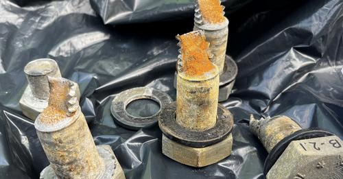
Are these bolt fractures consistent with the theory that the truss splayed outward and unzipped the bolts from top to bottom?
Edit 2: I don't know where these bolts were found and haven't read the article. The article is dated today, Sept 21. I note they have made considerable progress recovering the structure on either side of the river.
Edit: see Figure 3 on this page
Paywall article
havarikommisjonen undersoker bolter pa tretten bru gikk i 90 graders skjaerbrudd etter overbelastning

Are these bolt fractures consistent with the theory that the truss splayed outward and unzipped the bolts from top to bottom?
Edit 2: I don't know where these bolts were found and haven't read the article. The article is dated today, Sept 21. I note they have made considerable progress recovering the structure on either side of the river.
Edit: see Figure 3 on this page
croberts.com said:The 45 degree full-slant fracture surface indicates high tensile loads. The fine, gray appearance of the fracture surface is consistent with a sudden overload failure.


Another article regarding the recovered bolts - no paywall
The Accident Investigation Board with preliminary results after the bridge collapse at Tretten
The Accident Investigation Board with preliminary results after the bridge collapse at Tretten
Accident investigation commission and first report (in Norwegian)
Undersøkelse av brukollapsen ved Tretten i Øyer kommune i Innlandet
INFORMASJONSSKRIV NR. 1: FORELØPIGE UNDERSØKELSER AV BRUKOLLAPSEN VED TRETTEN 15. AUGUST 2022
Undersøkelse av brukollapsen ved Tretten i Øyer kommune i Innlandet
INFORMASJONSSKRIV NR. 1: FORELØPIGE UNDERSØKELSER AV BRUKOLLAPSEN VED TRETTEN 15. AUGUST 2022
From the report, regarding the recovered bolts (using Google Translate)
Report on examination of bolts from Tretten bridge
SINTEF has so far received and examined 21 half-bolts that were used between trusses and cross-beams on
Thirteen bridges. The bolts were retrieved from the river in the area around axis 3 (see figure 2). It was quality M24 bolts
8.8 and M27 bolts of quality 10.9.
All M24 bolts received (14 halves out of 48 possible) have a shear fracture 90° on the longitudinal axis, and have
probably been sheared by relative movement in the plane between the cross member and the knot in the truss that they tied
together. All M27 bolts have fractures caused by tension/bending movement in the bolt's longitudinal axis.
Furthermore, no signs of fatigue or previous damage have been observed on the bolts received, and the fractures show
ductile behavior for both bolt classes. Overall, this indicates that the bolts received have broken
as a result of overloading when the bridge collapsed.
At this point in the investigation, it cannot be ruled out that there may be other bolts than those examined
been subject to fatigue or failure that has developed over time.
Rapport om undersøkelse av bolter fra Tretten bru
SINTEF har til nå mottatt og undersøkt 21 halve bolter som ble benyttet mellom fagverk og tverrbærere på
Tretten bru. Boltene ble hentet opp fra elva i området rundt akse 3 (se figur 2). Det var M24 bolter av kvalitet
8.8 og M27 bolter av kvalitet 10.9.
Samtlige mottatte M24 bolter (14 halvdeler av 48 mulige) har et skjærbrudd 90° på lengdeaksen, og har
trolig blitt klippet over av relativ bevegelse i planet mellom tverrbæreren og knuten i fagverket som de bant
sammen. Samtlige M27 bolter har brudd forårsaket av strekk/bøy-bevegelse i boltenes lengdeakse.
Videre er det ikke observert tegn til utmatting eller tidligere skader på de mottatte boltene, og bruddene viser
duktil oppførsel for begge bolteklasser. Samlet sett indikerer dette at de mottatte boltene har gått til brudd
som følge av overbelastning da brua kollapset.
Det kan på dette tidspunktet i undersøkelsen ikke utelukkes at andre bolter enn de som er undersøkt kan ha
vært gjenstand for utmatting eller feil som har utviklet seg over tid.
- Status
- Not open for further replies.
Similar threads
- Replies
- 0
- Views
- 3K
- Replies
- 13
- Views
- 13K
- Replies
- 17
- Views
- 11K
- Replies
- 33
- Views
- 3K
- Replies
- 1
- Views
- 862

