I have not seen this posted.
Navigation
Install the app
How to install the app on iOS
Follow along with the video below to see how to install our site as a web app on your home screen.
Note: This feature may not be available in some browsers.
More options
Style variation
-
Congratulations cowski on being selected by the Eng-Tips community for having the most helpful posts in the forums last week. Way to Go!
You are using an out of date browser. It may not display this or other websites correctly.
You should upgrade or use an alternative browser.
You should upgrade or use an alternative browser.
Norway bridge collapse 17
- Thread starter dylansdad
- Start date
- Status
- Not open for further replies.
LittleInch said:Do bridges assume even traffic flow in both directions?
Absolutely. They do in the States, at least, and I'm positive they do in Europe as well. The number of live load cases a bridge engineer has to run through is mind boggling.
As for the bolt patterns - the geometry changes along the length of the bridge, so the connection geometry and layout also has to change.
Separating the road deck from the structural was likely the result of thermal stress analysis. The road deck with it's large surface area and black asphalt would likely heat up much faster than the chords, resulting in a significant differential in the thermal expansion of the structure. Tie it all together, and you'd buckle the road deck the first summer in service. It is possible that some sort of dynamic response was amplified/ exacerbated by decoupling the two parts of the structure - that's a bit beyond my expertise.
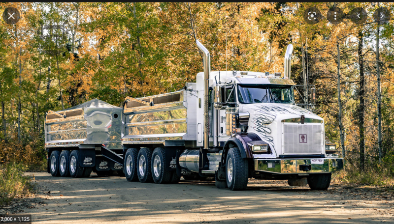
That truck is not large and there is only one. Below is a common NA truck. That is a tri-axle truck with a tri-axle pump. It holds approx 30cuyd of gravel or 97,000lb. On my travel thru Norway I do not recall seeing any of these, but they have some nearing that size. The truck was likely the instigating factor here, but given the bridge has been standing for 10yrs, it is very likely it had been subjected to one or more of these in the past. I would expect there is some amount of degradation of critical joints and/or joints where the capacity was not quite what they expected. I think we will need to wait to see the final report.
The video by Consult was not stellar, but they did dig up a number of interesting pictures I had not seen. I find the joints fascinating. They seem feasible in a shop setting, but how one can work to the tolerances needed in the field seems very challenging. The failures where the core was left behind is interesting, but without a lot more information I do not think we can draw any concrete conclusions from that.
The video by Consult was not stellar, but they did dig up a number of interesting pictures I had not seen. I find the joints fascinating. They seem feasible in a shop setting, but how one can work to the tolerances needed in the field seems very challenging. The failures where the core was left behind is interesting, but without a lot more information I do not think we can draw any concrete conclusions from that.

Brad805 said:but without a lot more information I do not think we can draw any concrete conclusions
Most intelligent thing anyone has said in this thread.
Short translation:
There have been at least 13 (tretten...) heavy transports needing special permissions for crossing the bridge previously. The heaviest weighing 97 tonns (970 kN / 213848 lb).
The bridge is designed for "Inter Nordics traffic loads" and even the 97 tonns shouldn't have been an issue.
-
1
- #166
-
1
- #168
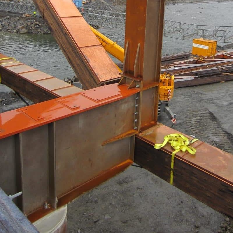
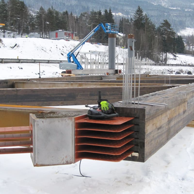
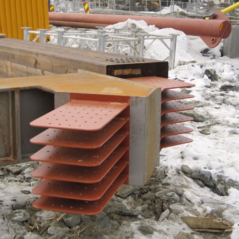
Great pics Sym. P. Ie. I would have thought they would need tighter tolerances than this for these connections to work. The tolerances here are no different than what we use for bolted steel connections. Easily done in the field working on un-level surfaces. Wood is far less forgiving with repetitive loading when you have sloppy joints. This is not my cup o tea for sure. I see glue lines very close to the knife plates. The level of confidence in these connections is dumbfounding to me given the importance of the structure.
I would think with a proper adhesive, the location of the steel plates relative to the joints would not matter much. To me the big problem is lining up the holes in the wood with the holes in the metal. The corner radius on the plates is similar to the radius on a chainsaw, maybe. I've never seen connections like this.
It appears to have a primer and does not appear to be Corten type weathering steel.
So strange to see the singularity approaching while the entire planet is rapidly turning into a hellscape. -John Coates
-Dik
It appears to have a primer and does not appear to be Corten type weathering steel.
So strange to see the singularity approaching while the entire planet is rapidly turning into a hellscape. -John Coates
-Dik
dik - only the knife plates are painted. The rest are left uncoated and do appear to be weathering steel. I'm guessing there was some concern about the development of the protective corrosion layer in the connection? Maybe they thought that small amount would be enough to initiate oxide jacking and split the glulams?
My error... I think you're correct about the coating; that's the reason I thought they were coated; just missed the steel outside of this. I thought the hole lineup would be the real tricky thing, too.
Contrary to the Youtube clip, I think a lot of thought went into this detail.
So strange to see the singularity approaching while the entire planet is rapidly turning into a hellscape. -John Coates
-Dik
Contrary to the Youtube clip, I think a lot of thought went into this detail.
So strange to see the singularity approaching while the entire planet is rapidly turning into a hellscape. -John Coates
-Dik
A "lot of thought" does not always translate to good answers. Any heavy timber structures I have been involved in always used bearing for compression connections, and a kind of load spreader (split rings or shear plates) for bolted tension connections. Simple bolted connections require clamping perpendicular to the main bolts, usually by transverse bolts, which require retightening after shrinkage.
Testing? What's that? The computer model says it is fine, so run with it.
Much like the Florida pedestrian bridge. That was at ground level, would have been easy to load test the full scale novel design before erection, but they were confident.
Much like the Florida pedestrian bridge. That was at ground level, would have been easy to load test the full scale novel design before erection, but they were confident.
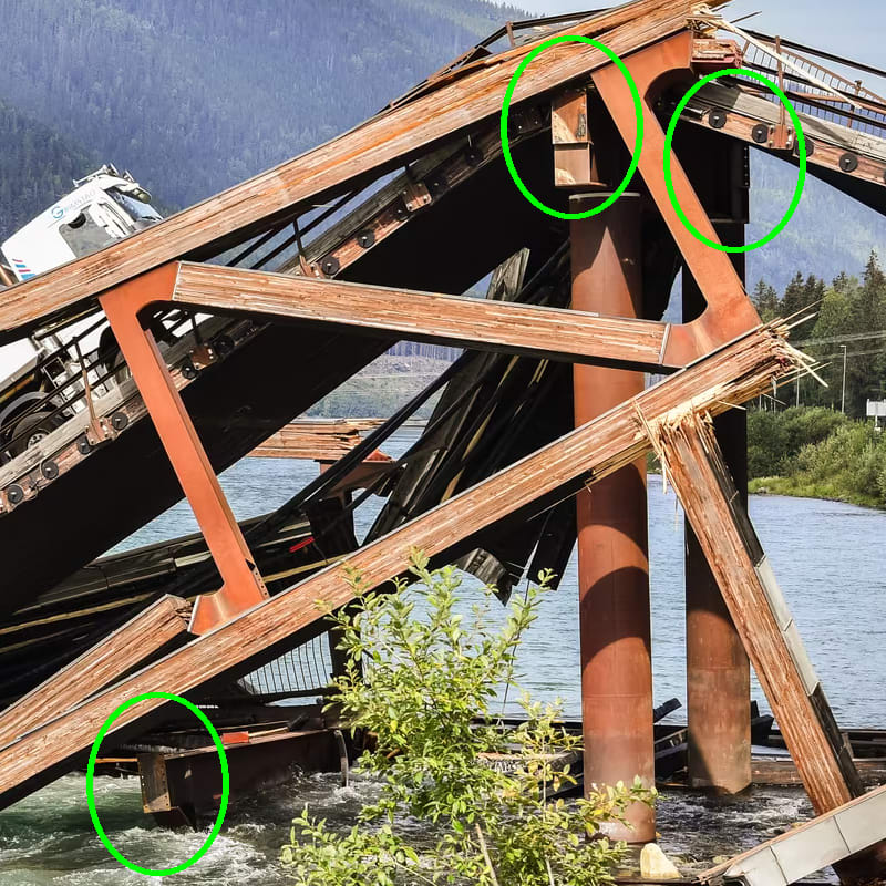
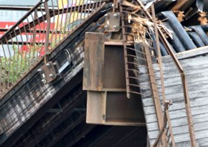
It can't be missed that at the east end of the structure, three bolted connections popped their bolts with nary a whimper. I believe this is also accounted for by the splitting of the lower chord at the stone support. As the connection (node 13 at the stone support) no longer offers resistance to the lateral "compression" force, the structure sags and the lower chord presses past the connection. The loss of form in the structure is compensated at the east end supports by splaying the tops of the truss members out and simply unzipping the bolted connections. Once the truss members push beyond the support tab on the vertical components, the east end is free to drop.
The implication is that the structure eased into the failure, at least initially, and this would give the truck driver that uphill feeling as he continued to travel east.

The implication is that the structure eased into the failure, at least initially, and this would give the truck driver that uphill feeling as he continued to travel east.


LittleInch
Petroleum
If one of those bolted connections to the new steel support had failed, would the bridge still work?
The key for me is to figure out what this "bouncing" was that was reported in the weeks beforehand.
Few structures fail without warning, it's just the warnings weren't taken seriously.
Remember - More details = better answers
Also: If you get a response it's polite to respond to it.
The key for me is to figure out what this "bouncing" was that was reported in the weeks beforehand.
Few structures fail without warning, it's just the warnings weren't taken seriously.
Remember - More details = better answers
Also: If you get a response it's polite to respond to it.
The bolts are not the primary support mechanism for the structure, they just keep things together so the vertical elements can do their job. They are obviously victims of the collapse, not a cause. It is also unlikely that the support tabs failed. They might still be as pristine as the bolt plates.
Sym, I am not sure how you come to "bolts are not the primary support mechanism for the structure.."? If the bolt holes elongate under compressive stresses that means the distance between the nodes is not fixed (ie. spring). All of those holes and slots are oversized for fit, so I do not think the members would immediately become bearing elements if the bolts are not adequate. The member itself may not fail under compressive stresses, but if you add partial fixity to one or more of your truss nodes you will find very different forces in your truss model. Without the compressive elements the truss behavior will be more like a vierendeel truss. There does not appear to be any redundant members in this truss.
LI, the problem with the layperson reports is most believe structures like this do not deflect. Unless someone hires someone to quantify that movement there is not much one can do with those reports. It takes it getting to the point of galloping girtie before some in power act on those reports.
LI, the problem with the layperson reports is most believe structures like this do not deflect. Unless someone hires someone to quantify that movement there is not much one can do with those reports. It takes it getting to the point of galloping girtie before some in power act on those reports.
An interesting point. In the typical frame (being the cross beam and vertical truss components), the bolts do carry the load as the cross beam generally hangs off the vertical members. However, at the two structural supports the role of the cross beam is reversed and the weight of the truss is borne by the tabs welded onto the vertical members (or perhaps in combination with the bolts).
I had only been looking at the connections over the supports.
I had only been looking at the connections over the supports.
- Status
- Not open for further replies.
Similar threads
- Replies
- 13
- Views
- 13K
- Replies
- 17
- Views
- 11K
- Replies
- 33
- Views
- 3K
- Replies
- 1
- Views
- 855
- Locked
- Question
- Replies
- 1
- Views
- 2K

![[pipe] [pipe] [pipe]](/data/assets/smilies/pipe.gif)