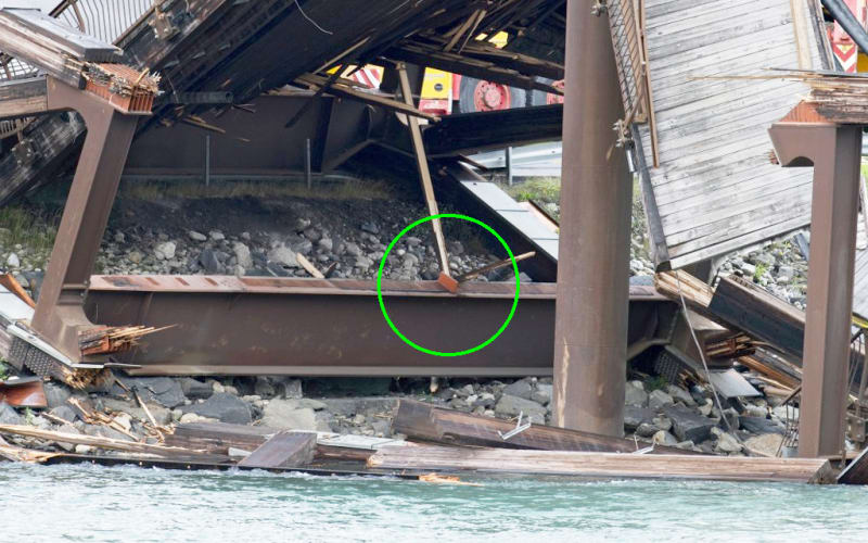
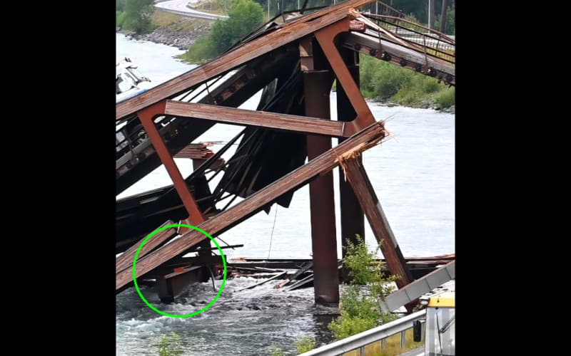
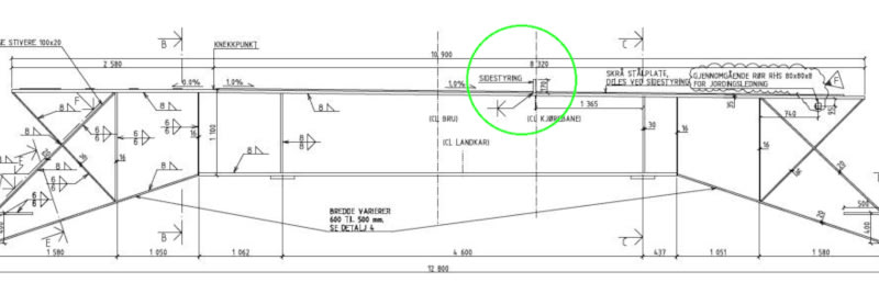
I have not seen this posted.
Navigation
Install the app
How to install the app on iOS
Follow along with the video below to see how to install our site as a web app on your home screen.
Note: This feature may not be available in some browsers.
More options
Style variation
-
Congratulations cowski on being selected by the Eng-Tips community for having the most helpful posts in the forums last week. Way to Go!
You are using an out of date browser. It may not display this or other websites correctly.
You should upgrade or use an alternative browser.
You should upgrade or use an alternative browser.
Norway bridge collapse 17
- Thread starter dylansdad
- Start date
- Status
- Not open for further replies.
spsalso said:Might be a good idea to use standoffs under that copper sheathing.
Upside: water gets in, airflow lets it dry.
Downside: gap large enough to ensure airflow is also a gap large enough to permit wind driven rain, increasing the amount of water that gets in.
Trick is finding a balance.
LittleInch
Petroleum
This bridge stood the for ten years so was clearly not designed that badly.
I wonder though whether the long term settlement of the new supports or strain on all these connections was allowed for and any longterm creep in the glulam so the bridge just became a little bit less rigid than it was when first built.
Remember - More details = better answers
Also: If you get a response it's polite to respond to it.
I've not done any research in it, but with material other than copper, it might be a good idea to have a gap on all sides. With copper, I think you would want intimate contact. Capillary flow would help insure the wood got wet, I suspect. Then the properties of copper would take over. I'm not a wood guy, and was unaware the AWC recommends on cladding.
I was aware of the brittle failure mode of wood... the only thing that outdoes it is glass, or cast iron, maybe. I was trying to point out that the tensile strength of wood fibres without any discontinuities, is really quite high. Defects have a real impact on it.
Contrary to the video, it appears the system used was well thought out. I'm still not sure why the failure occurred. I've never used that type of connection and was unaware it even existed.![[ponder] [ponder] [ponder]](/data/assets/smilies/ponder.gif)
So strange to see the singularity approaching while the entire planet is rapidly turning into a hellscape. -John Coates
-Dik
I was aware of the brittle failure mode of wood... the only thing that outdoes it is glass, or cast iron, maybe. I was trying to point out that the tensile strength of wood fibres without any discontinuities, is really quite high. Defects have a real impact on it.
Contrary to the video, it appears the system used was well thought out. I'm still not sure why the failure occurred. I've never used that type of connection and was unaware it even existed.
![[ponder] [ponder] [ponder]](/data/assets/smilies/ponder.gif)
So strange to see the singularity approaching while the entire planet is rapidly turning into a hellscape. -John Coates
-Dik
dik - sorry, the comment on wood failure modes wasn't really directed at you.
And yes - knife plates with pins is very common with glulam construction. A lot of glulam construction is left exposed, so architects like to hide the steel. You're often left with a bolt head/nut in a counter bored hole. Though, as I know you know, wood likes lots of little fasteners more than a few big ones.
And yes - knife plates with pins is very common with glulam construction. A lot of glulam construction is left exposed, so architects like to hide the steel. You're often left with a bolt head/nut in a counter bored hole. Though, as I know you know, wood likes lots of little fasteners more than a few big ones.
I have used them once, on a timberframe structure where the client didn't want to see connections. I used internal steel plate with a pair of ironwood 'pegs'. It was great until the contractor, who picked up a Japanese 'pull saw' trimmed the pins off flush with the timber. I hadn't noted on my drawings that the pins should protrude for appearance... only time. Timberframe is my favourite type of structure.
So strange to see the singularity approaching while the entire planet is rapidly turning into a hellscape. -John Coates
-Dik
So strange to see the singularity approaching while the entire planet is rapidly turning into a hellscape. -John Coates
-Dik
It is very unlikely that the member was ever a tension member, except, maybe, when the truck was on the first span and the tensile load on the member would be quite small. Failure likely occurred when the truck was on the second span and the member would definitely be in compression (big time). Failure, without doing the sums, was likely caused by overload or deterioration of the wood structure causing an overload condition.
![[pipe] [pipe] [pipe]](/data/assets/smilies/pipe.gif)
So strange to see the singularity approaching while the entire planet is rapidly turning into a hellscape. -John Coates
-Dik
Deterioration. In ten years. I've got food that lasts longer than that.
I note that there's nothing on-line by "the investigating authority". Wonder how long that's going to take. Shouldn't be too long, as they likely can't build any more of those super cool wood bridges until they figure out how come they fall down.
spsalso
I note that there's nothing on-line by "the investigating authority". Wonder how long that's going to take. Shouldn't be too long, as they likely can't build any more of those super cool wood bridges until they figure out how come they fall down.
spsalso
There are several strains of 'brown rot'; some are much more aggressive. Some can cause damage in only a few years. By the time you observe/notice it, there may be significant deterioration. Catch the 'blurb'...
[URL unfurl="true"]https://res.cloudinary.com/engineering-com/image/upload/v1663199294/tips/Brown_Rot_22-07-19_jg6yti.pdf[/url]
So strange to see the singularity approaching while the entire planet is rapidly turning into a hellscape. -John Coates
-Dik
[URL unfurl="true"]https://res.cloudinary.com/engineering-com/image/upload/v1663199294/tips/Brown_Rot_22-07-19_jg6yti.pdf[/url]
So strange to see the singularity approaching while the entire planet is rapidly turning into a hellscape. -John Coates
-Dik
dik - I have to say, though, the failed member condition is compelling and looks like a tension failure. That said...if the dowels were overloaded and yielded, it could conceivably cause a connection failure in compression before buckling of the member. It would cause the pins to yield and bend toward the ends of the web member and would effectively shorten the distance between connections while the member length stays the same. Then, when the load is removed, the connections (which are rigidly connected to the larger joint weldment) want to return to their original positions and move back out. Well those yielded pins would act like the barbs on a fishing hook and do more damage coming out than they did going in. Thus leaving that member essentially unconnected but still looking "okay" to the casual observer.
One concern that I have for that kind of connection in a bridge (and something that was never brought up in that video) would be fatigue of the pins. They work great in buildings, but fatigue isn't an issue in typical building design. A web member connection on a truss, it's a bit more important. The small diameter pins would likely see pretty high stresses, and cycling could certainly bring about fatigue failure. (Weathering steels are subject to fatigue under pulsating loads, so even if it never reversed you can still develop fatigue failures.) I could certainly see this being a problem. I'd have to dig through ASSHTO (I don't use it often...at all, really) but last time I looked it appeared as though they copy and pasted the NDS. The NDS has nothing about fatigue. The connection designs look at yield modes, but let's face it - a lot of structural engineers don't know what IIIm means. Obviously this bridge wasn't designed using either of those codes for reference, but it's worth thinking about - especially for those of us who may find one of these on our desk one day.
One concern that I have for that kind of connection in a bridge (and something that was never brought up in that video) would be fatigue of the pins. They work great in buildings, but fatigue isn't an issue in typical building design. A web member connection on a truss, it's a bit more important. The small diameter pins would likely see pretty high stresses, and cycling could certainly bring about fatigue failure. (Weathering steels are subject to fatigue under pulsating loads, so even if it never reversed you can still develop fatigue failures.) I could certainly see this being a problem. I'd have to dig through ASSHTO (I don't use it often...at all, really) but last time I looked it appeared as though they copy and pasted the NDS. The NDS has nothing about fatigue. The connection designs look at yield modes, but let's face it - a lot of structural engineers don't know what IIIm means. Obviously this bridge wasn't designed using either of those codes for reference, but it's worth thinking about - especially for those of us who may find one of these on our desk one day.
From the driver, Terje Brenden, dated Aug 17, 2022:
Google Translate - The Tretten bridge collapsed: - I was sure it was over!
Edit: car translates to bil, lorry or truck translates to lastebil
Google Translate - The Tretten bridge collapsed: - I was sure it was over!
Terje Brenden is employed by the NLF company Sigurd og Ola Grimstad AS. Brenden will not speak to the media. He only gives this comment to lastebil.no.
I was in the middle of the bridge when I noticed something on the car. Almost as if it had punctured. Then the asphalt began to wave up and down in front of me - almost like you see an earthquake. Suddenly it became so steep that I couldn't get any further, says Brenden to Lastebil.no.
Terje Brenden er ansatt i NLF-bedriften Sigurd og Ola Grimstad AS. Brenden vil ikke uttale seg til mediene. Han gir kun denne kommentaren til lastebil.no.
Jeg var midt på brua, da jeg merket noe på bilen. Nesten som om den hadde punktert. Så begynte asfalten å bølge opp og ned foran meg – nesten som du ser et jordskjelv. Plutselig ble det så bratt at jeg kom ikke lenger, sier Brenden til Lastebil.no.
Edit: car translates to bil, lorry or truck translates to lastebil
From my earlier post, abnormal movements in the Tretten bridge before the collapse
Coupled with the truck drivers account, is it possible that a particular moving load could create a wave that causes catastrophic damage in an otherwise statically sound structure? From the truck drivers comment it sounds that he was closer to the reused stone support (technically closer to center of overall stucture) when the event initiated.
Also, the road deck is a continuous laminated wooden mat that runs the length of the structure and appears rather loosely attached to the steel framework beneath. Could this develop its own secondary oscillation and detach from the steel structure?
Anita Bakken lives at Tretten. She has experienced abnormal movements in the bridge when there have been lorries on it with her. – There has been a kind of rocking in the bridge recently, which has not been there before. She says that several people have noticed the same thing. Both those who have walked, cycled or driven over the bridge and encountered heavier vehicles. news has also spoken to several people who say they have experienced abnormal movements.
Coupled with the truck drivers account, is it possible that a particular moving load could create a wave that causes catastrophic damage in an otherwise statically sound structure? From the truck drivers comment it sounds that he was closer to the reused stone support (technically closer to center of overall stucture) when the event initiated.
Also, the road deck is a continuous laminated wooden mat that runs the length of the structure and appears rather loosely attached to the steel framework beneath. Could this develop its own secondary oscillation and detach from the steel structure?
The unfortunate trailer spacing on the lorry could play a significant role in the structural collapse by causing oscillations through the road deck:
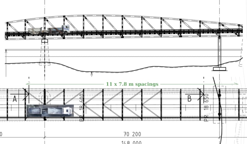
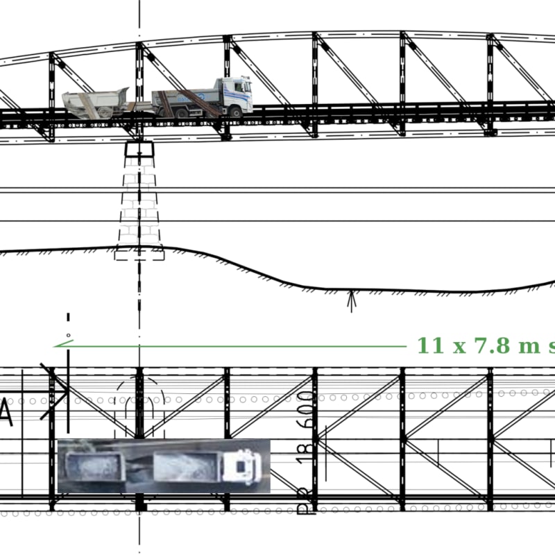
(I've done my best to accurately reproduce the scale of the lorry to that of the structure)


(I've done my best to accurately reproduce the scale of the lorry to that of the structure)
As I was developing earlier in the thread, the detachment of the lower chord from the reused stone support would result in the collapse results seen at the support. By the time the truck reaches the center of the structure, it has already bounced 7 or 8 times, and this after ten years of these trucks doing the same?
The nine meter section found 15km downstream bears the markings of the lower chord at the stone support, five pins and slots for the diagonals cut longer on one side of the pins than the other (indicating the exposed end is the west end). There aren't many locations this piece could come from.

Question - Are the trucks usually heading out loaded in one direction and returning empty in the other?
The nine meter section found 15km downstream bears the markings of the lower chord at the stone support, five pins and slots for the diagonals cut longer on one side of the pins than the other (indicating the exposed end is the west end). There aren't many locations this piece could come from.

Question - Are the trucks usually heading out loaded in one direction and returning empty in the other?
For those that don't see it, the axle spacing between the lorry and trailer are too similar to the steel frame spacing. The road deck, which is not fastened to the steel frames, is free to flex as it will so the lorry/trailer rise and fall synchronously over and between each steel frame, amplifying their abuse with each passing frame. I don't know if the forward velocity would come into play.
I still lean toward the lower chord splitting at the stone support since the pins are not free to move or rotate with the chord. They present themselves as a pry to the chord fibers. I see this small issue with disastrous results easier to believe than having one of the heavier and more studied connections blowing out.
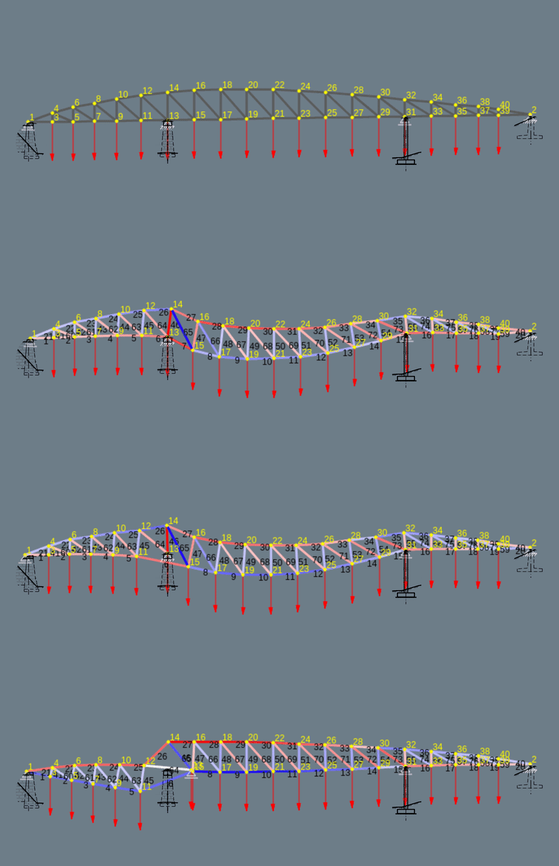
I've added an overlay of the support drawings to my gif (same scenario as I posted earlier with extra load at 13/15 for the lorry) in case it makes it easier to understand. I can't make it replicate the fall, just indicate components of failure mechanism. It doesn't bring all the answers.

Alistair_Heaton
Mechanical
Well the ones I see near me during transport season all go one way loaded and empty the other.
As you say the timber trailers are not your normal lorry trailer suspension.
If the norgie drivers are anything like the ones round me they slow down for nothing but a speed limit sign and that's to due digital tacho.
If there isnt a speed reduction for the bridge they will hit it at the road speed limit.
Most of the driver's and labour will more than likely be from round me anyway.
It's lethal on the logging routes when it's your areas turn.
LittleInch
Petroleum
You could be something in that as it look like the laden truck direction is the one on the edge of the width which is offset to allow for the footpath. so distinctly uneven loading which may not have been considered? Do bridges assume even traffic flow in both directions?
Also I've noticed a wide variety in the top chord for the connection details, which seems to be every 4 bays, in terms of bolts going from west to east and bolts horizontal x V, and changes sometimes either side of the joint it goes
3x5 4x5,
3x5 3x5
2x3 2x3
5x6 4x4
4x5 4x5
Remember - More details = better answers
Also: If you get a response it's polite to respond to it.
- Status
- Not open for further replies.
Similar threads
- Replies
- 13
- Views
- 13K
- Replies
- 17
- Views
- 11K
- Replies
- 33
- Views
- 3K
- Replies
- 1
- Views
- 853
- Locked
- Question
- Replies
- 1
- Views
- 2K

