I have not seen this posted.
Navigation
Install the app
How to install the app on iOS
Follow along with the video below to see how to install our site as a web app on your home screen.
Note: This feature may not be available in some browsers.
More options
Style variation
-
Congratulations cowski on being selected by the Eng-Tips community for having the most helpful posts in the forums last week. Way to Go!
You are using an out of date browser. It may not display this or other websites correctly.
You should upgrade or use an alternative browser.
You should upgrade or use an alternative browser.
Norway bridge collapse 17
- Thread starter dylansdad
- Start date
- Status
- Not open for further replies.
I was trying to be funny... but failed, I guess. You cannot avoid it sometimes... a bigger problem occurs with metal side plates and bolts when the lumber shrinkage tends to cause the lumber to crack.
So strange to see the singularity approaching while the entire planet is rapidly turning into a hellscape. -John Coates
-Dik
So strange to see the singularity approaching while the entire planet is rapidly turning into a hellscape. -John Coates
-Dik
I thought maybe.
I think that pipe smoking emoticon is supposed to say "wisdom", or something like that.
I'm not finding a great "I'm being funny" one, though.
Yeah. I think with bolts you're supposed to have a jolly worker tighten them up once in awhile. The "nice" thing about using these pins is you can't. Labor saving, you know.
Ed
I figure they are (mostly) pins because:
I see no noticeable heads or nuts in those locations--just an array of small holes.
And.
On page 11 of the linked document "What went wrong?" (posted by Sym P. le about 24 posts ago), there is reference to 12mm dowels:
"The tension belt is joined using 4 (12 mm thick) slotted steel plates and 24 steel dowels in 6 rows along the fiber direction. The dowels have a diameter of 12 mm and a characteristic tensile strength fu,k = 900 MPa. It is assumed that the plates sit in slots that are 14 mm wide. Detail of a dowel is shown schematically in figure 6. When calculating the characteristic capacity for a dowel, it is natural to consider the inner fields (A) and the outer fields (B) separately."
I assume that the Tretten bridge used similar connections. They certainly look similar to me.
spsalso
LittleInch
Petroleum
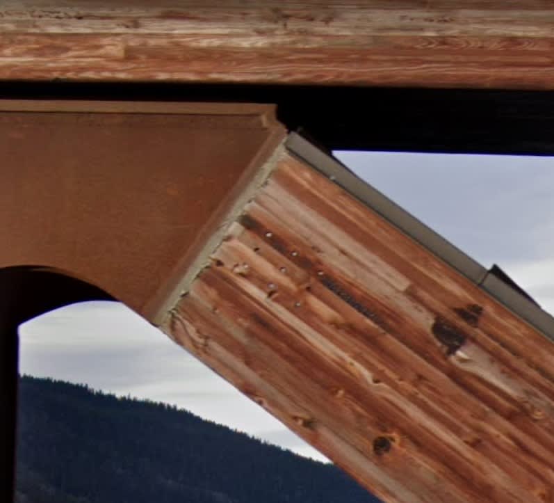
It looks to me like the bridge was actually built in lots of three or four bays pre fabricated off side and hence they use the pins / dowels on those connections and then bolted into position with the finned multiplate connections. So the connections at those nodes I guess are a bit different to the others. you can spot the connections easily on street view.
More by luck than otherwise it seems one of those connections is right where the stone pillar is.
Also I'm not sure which node this is but its towards the western end and I'm sure it wasn't supposed to look like this...
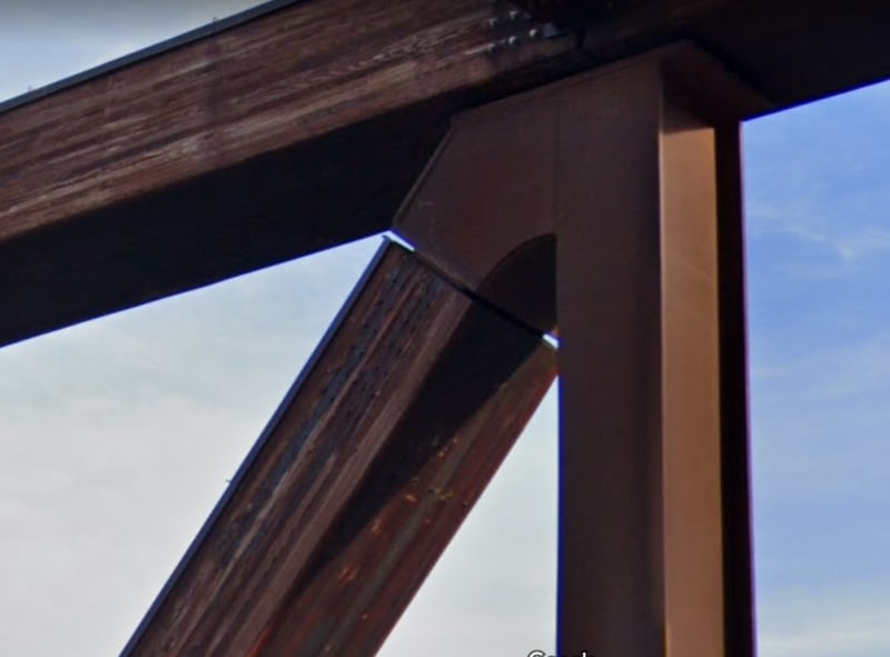
Also it's opposite neighbour.
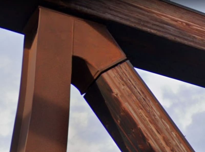
And some seem to have been "sealed". So don't know which is correct?
Remember - More details = better answers
Also: If you get a response it's polite to respond to it.
More by luck than otherwise it seems one of those connections is right where the stone pillar is.
Also I'm not sure which node this is but its towards the western end and I'm sure it wasn't supposed to look like this...

Also it's opposite neighbour.

And some seem to have been "sealed". So don't know which is correct?

Remember - More details = better answers
Also: If you get a response it's polite to respond to it.
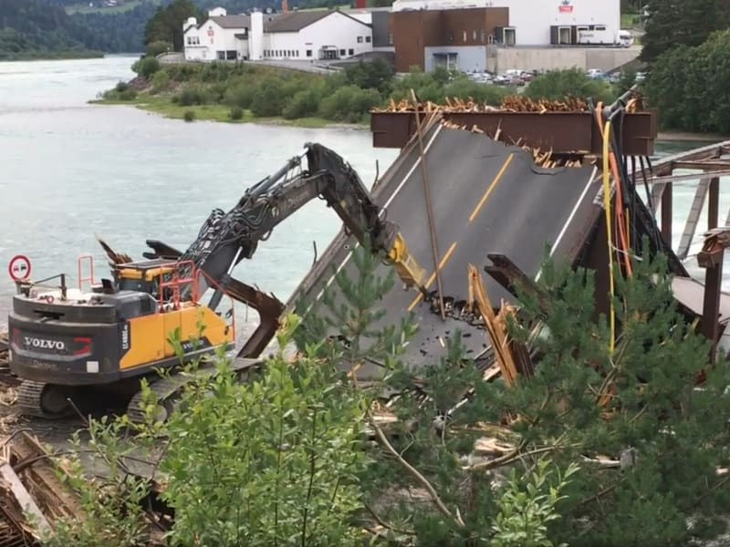
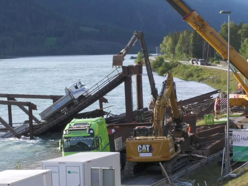
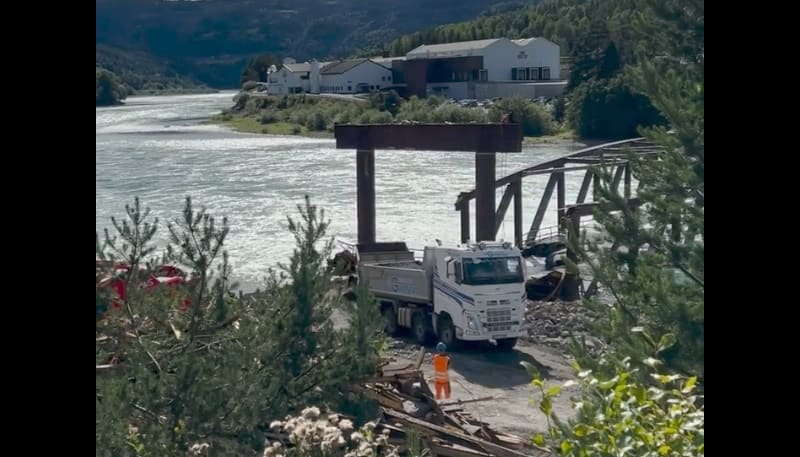
They got the truck outta there! I mean they actually drove it out! They might want to have a mechanic look over the suspension.
Facebook video
Facebook video
Facebook video
also
Edit: They winched it off the deck and then drove it away.

Facebook video

Facebook video

Facebook video
also
Edit: They winched it off the deck and then drove it away.
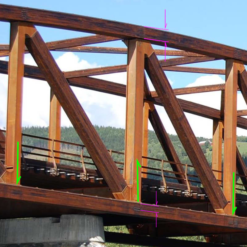
Please allow me one more attempt to convey my thoughts on the problem support.
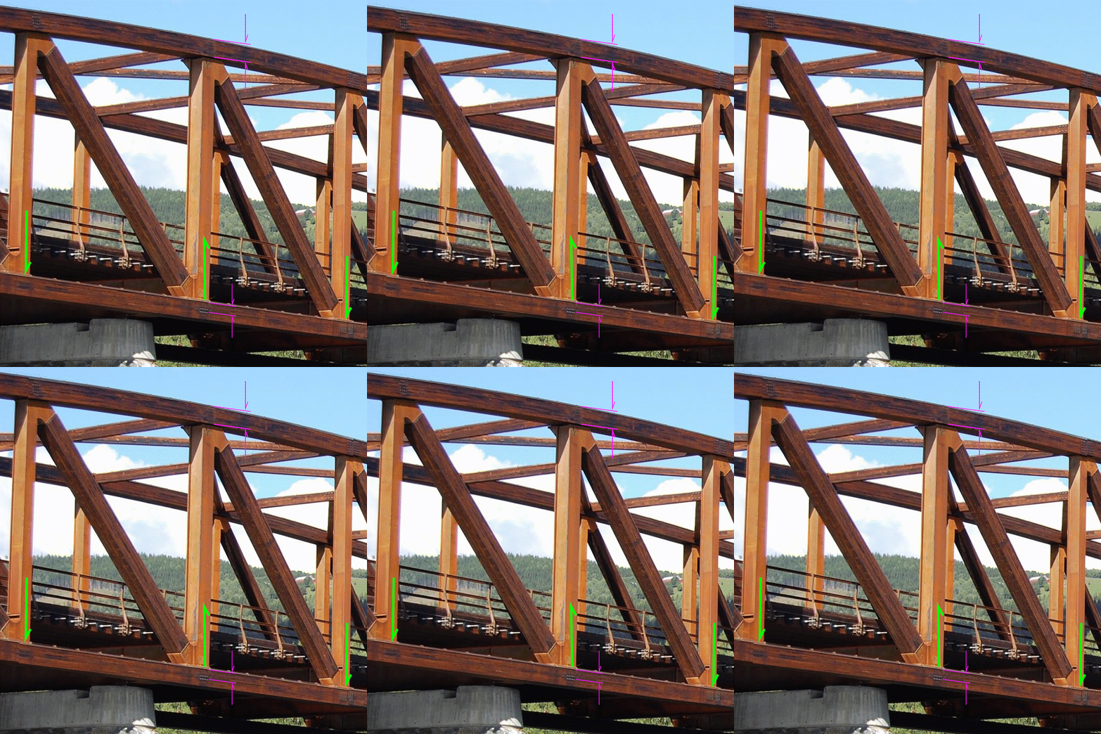
When the structure flexes, the full depth of the top chord is engaged (vertically) whereas only the top portion of the lower chord is engaged. I see this as a driver for splitting the lower chord and crippling the chord's ability to support the compressive loads it carries.
When the structure flexes, the full depth of the top chord is engaged (vertically) whereas only the top portion of the lower chord is engaged. I see this as a driver for splitting the lower chord and crippling the chord's ability to support the compressive loads it carries.


Splitting of the chord is a possibility, but I don't see it at this node. This node has light forces other than axial compression. That's why there are just a few dowels in the chord. Axial compression is taken by the chord which is continous. Diagonal on the other hand is loaded heavily in tension.
There is no load hanging directly on the chord, as I see it, but rather on steel cross beams which are part of the verticals in the trusses.
There is no load hanging directly on the chord, as I see it, but rather on steel cross beams which are part of the verticals in the trusses.
"A review of the country's wooden truss bridges, including Tretten Bridge, was previously conducted in 2016 following the collapse of Perkolo Bridge another timber crossing also in Gudbrandsdalen.
It found "no significant errors" (translated from Norwegian) with Tretten Bridge but recommended that one of its joints be strengthened and some dowels replaced."
A four year old bridge needing a joint strengthened and some dowels replaced. What could have damaged the dowels in four years such that they needed replacing?
The bridge designers are architects. Might want to hear from the structural engineers who helped out a bit.
spsalso
I believe that would be this one from September 2016 - Kontroll av fagverksbruer i tre.pdf - Inspection of wooden truss bridges Discussions, findings and recommendations from the work. I'm not familiar with Norwegian but with the help of Google Translate, I came up with the following.
From page 8,
The report talks of brittle fracture (sprøbrudd) and block stripping (Blokkutriving) of pin groups though it seems rather confused about the urgency. I wasn't able to gain any insight which junctions in the Tretten bridge may be affected.
Diagonal 5 connects at node 13 (at the support). I wonder if the extended pins are what we see in the image I used above (in the upper and lower chords) which was posted May 2, 2016.
It will be interesting to see what gets pulled out of the water with regards to damages at the nodes near the support.
From page 8,
Tretten
Det er ikke oppdaget feil av betydning i kontrollberegningene. Det er funnet noen få større overskridelser i utnyttelse i forhold til nytt regelverk. Dette er ingen prosjekteringsfeil, men da vi ikke har tilstrekkelig kunnskap om bakgrunnen for regelendringene anbefales det å forsterke de knutepunktene dette gjelder.
Inspeksjonen oppdaget noen for korte dybler i diagonal 5. Diagonalen står i trykk og overfører kreftene ved direkte opplegg. De forkorte dyblene har liten betydning for kapasiteten, men er bestilt utskiftet.
Thirteen
No significant errors have been detected in the control calculations. A few major excesses in utilization compared to the new regulations have been found. This is not a design fault, but as we do not have sufficient knowledge of the background for the rule changes, it is recommended to strengthen the junctions to which this applies.
The inspection discovered some dowels that were too short in diagonal 5. The diagonal is in pressure and transfers the forces by direct installation. The shortened dowels have little significance for the capacity, but have been ordered replaced.
The report talks of brittle fracture (sprøbrudd) and block stripping (Blokkutriving) of pin groups though it seems rather confused about the urgency. I wasn't able to gain any insight which junctions in the Tretten bridge may be affected.
Diagonal 5 connects at node 13 (at the support). I wonder if the extended pins are what we see in the image I used above (in the upper and lower chords) which was posted May 2, 2016.
It will be interesting to see what gets pulled out of the water with regards to damages at the nodes near the support.
spsalao said:What could have damaged the dowels in four years such that they needed replacing?
Nothing according to the papers, the bridge was design with the now outdated Norwegian codes, but constructed after Eurocodes were implemented. The codes differs on dowels.
LittleInch
Petroleum
I'm drawn back to that excert from Brad805 on 18th August where the perhaps over reliance on computer modelling is a factor, especially I think here where it is clear that 10 years of traffic and rain / snow/ sun may have led to some of the joints becoming more err flexible than maybe the model assumed.
The two hard points in the bridge at the two supports I still think creates long term flexing around those points, especially with the construction joints being very close to them.
If would also be interesting if they actually looked at the construction models in design to see where those construction joints were.
Remember - More details = better answers
Also: If you get a response it's polite to respond to it.
From New Civil Engineer:
LittleInch
Petroleum
So basically they haven't really got a clue either....
I do hope they are trying to preserve things as much as they can when removing sections of the bridge. That digger driver in the facebook posts doesn't seem to have got the memo....
The truck got dragged out, but was quite a neat way of removing it. It looks empty to me....
Remember - More details = better answers
Also: If you get a response it's polite to respond to it.
- Status
- Not open for further replies.
Similar threads
- Replies
- 13
- Views
- 13K
- Replies
- 17
- Views
- 11K
- Replies
- 33
- Views
- 3K
- Replies
- 1
- Views
- 853
- Locked
- Question
- Replies
- 1
- Views
- 2K
